
Contents
- 1 Two movies
- 2 20Oct2022 hiatus
- 3 Related notes
- 4 Intro
- 5 Background
- 6 Fold handling with Collapse-O-Matic plugin
- 7 Getting started log
- 8 My Beep-BRRR lab box
- 9 XMOS Libraries
- 10 Coding
- 11 Download code
- 12 Algorithm matters
- 13 GUI structure
- 14 DAC analog out alternatives
- 15 Extension I/O board
- 16 xSCOPE
- 17 The choices
- 18 Tools
- 19 Scratchpad
- 20 14.4.1 on a reserved machine!
- 21 Alternatives
- 22 Forums
- 23 [[TODO]]
- 24 References
New 02Apr2021. Updated 15Feb2024. This note is in group Technology, sub-group My Beep-BRRR pages. Last changes, newest on top, left:
|
|
Two movies
See My Beep-BRRR notes (movies). These movies show detecting an alarm as of 01Dec2022 and 09Jan2023. I show the result, even if I have a blogging/code hiatus. See next chapter.

20Oct2022 hiatus
I have a Beep-BRRR blogging pause at the moment. I need to think about how open I should be in the forthcoming weeks or months – about my final algorithmic stuff. The reason is that it «sounds like» the Beep-BRRR is now in fact recognising individual reference sounds that I record «in vivo». Quite selectively. Should I really give this code away for free? Or could I publish it here with limitations as to usage? But then, this might become a box that could actually help people? But then (again), I would not want to sell and then lose control? Please comment below or mail me.
Update 15Feb2024. See this chapter:
This note is (as malso entioned on the top) in sub-group My Beep-BRRR pages.
Intro
This note concerns use of the round XMOS microphone array board, with code in xC. If you code in C I hope there would still be much to read here. It’s not that xC’ish. This note is in group Technology. Observe Standard disclaimer.
Also see the stream of consciousness style disclaimer – since I’m afraid the structure is the result of what is happening as I am working on this project, right now. Especially: some problem described early may have a solution further down, which I may not have referenced down or up. The Contents table may help, though, plus searching in the text. In other words, this blog note exposes my private development process, where there are no reviews or UML component diagrams, as such. No nice Trello boards for spec points with timelines. But I do use some alternatives. Should this blog note get too bloated (it already is bloated), I probably will sum up in a new note when I’m finished.
Background
Icon download: PDF
Beep-BRRR is supposed to listen to alarm sounds of any kind and then vibrate into a bed’s structure to wake a sleeping person. A sleep that might not, due to some degree of hearing loss, have been interrupted without this remedy.
Thanks, Kenny in Scotland, for suggesting it to be three R’s in the BRRR, so that the English reader sees that all those R’s are rolling. Or feels them in the body. .
Yes, I know that there exist a lot of boxes that would do this. May plan was to let go with one.
Fold handling with Collapse-O-Matic plugin
| Collapse All |
Typical fold
Sound recognition
Update 4Mar2022. I had at first thought that I should listen and recognise several sounds by getting a recording of each of them, do an offline spectrum analysis to find the frequency components, load those spectra over to the Beep-BRRR unit – and then compare each of them with every frequency charts that I (hypothetically) were to make from microphone inputs, on the fly. I had come some way on this (getting a number on the display that increased linearly with a frequency from a tone generator (v0619, 28Feb2022) when I discovered a beautiful new function, starting on the Apple iPhone’s iOS 14.0 (Sep2020, so I am behind, as I am with not having started with the new XMOS.ai processors that have a built-in vector unit, meant for embedded machine learning, by f.ex. using TensorFlow). Having discovered the new function on the iPhones, maybe I now only need to listen for one sound only, coming from the iPhone crapped with neural engines, that already is on the bedside table. Enter..:
iOS «Sound Recognition»
Moved to the Alternatives section, iOS “Sound Recognition”.
xCORE microphone array
Update 8Mar2022: Message from Digi-Key: The XCORE MICROPHONE ARRAY EVALUATION BOARD XK-USB-MIC-UF216 has changed status to obsoleted (here). Luckily I have two, which is all I need. But buying an external PDM mic board, like [14] and using any xCORE development board will do the trick, I assume. Or, best of all, have a look at the XMOS Voice or Audio categories. I myself have an XK-VOICE-L71 pending future discoveries (here).
Apart from the real intro (discovering the need) this started with me asking some xCORE Microphone Array board questions on the XCore Exchange Forum. I then bought two boards DEV KIT FOR MICROPHONE ARRAY of type XK-USB-MIC-UF216 from XMOS. Let’s just call it MIC_ARRAY. I have grouped some boards in 151:[xCORE microphone array]
 Now I’ve made a box for one of them and mounted it on my desk. The other board will, if I succeed, end up at a bedside table, inside a wooden box. I have the box design also planned. So I’d better succeed!
For this application I don’t need the USB or Ethernet connectivity. What I’m basically left with then are these points:
Relevant contents
- xCORE-200 (XUF216-512-TQ128) multicore microcontroller device
- On version 2V0 of the board: seven INFINEON IM69D130 MEMS PDM (Pulse-Density Modulation) microphones [15]. On the older version(s?), the 10 dB more sensitive Akustica AKU441
- An expansion header for with I2S and I2C and/or other connectivity and control solutions
- These I2S and I2C lines are also used with the Cirrus Logic CS43L21 DAC [13] for the a stereo 3.5 mm headphone jack output
- Cirrus Logic CS2100-CP Fractional-N PLL [12]
- Four general purpose push-button switches
- 12 user-controlled red LEDs
- 2MByte QSPI FLASH is internal (on chip)
Seven PDM MEMS microphones
A MEMS microphone is an electronic chip where even the membrane that picks up the sound is made of silicon. On the MIC_ARRAY board six of these are placed around a radius of 45 mm at 60 degrees and one in the middle. In the XMOS application note AN00219_app_lores_DAS_fixed (more later) the file mic_array_das_beamformer_calcs.xls shows how the phase differences between the same signal coming in at 30° will differ by typically have a delay of 0.342 mm/µs → some 15 µs from one of the six microphones to the center. This may be used to hear where the source of the sound is. On that appnote I may set the delays and LEDs with the buttons such that, when I wear the headphones, I can hear myself loudest when the microphone array «points» to me. As the note says. «The beam is focused to a point of one meter away at an angle of thirty degrees from the plane of the microphone array in the direction indicated by the LEDs.».
The microphones will decide on a new digital output at (like) 48 kHz rate. This is done with a delta-sigma modulator (see Wiki-refs) that delivers a 50% on/off at zero, fully on at max and fully off at min. This is PDM or pulse-density modulation.
To «decimate» the 8 pulse trains we need a decimator or low-pass filter for each. The analogue equivalent is an R-C, where the pulse train is presented to the R and the analogue value appears on the C. Then one would apply an A/D converter, but this functionality is built into the sw decimators. Each decimator handles four channels. They all output 16 or 32 bit samples, at some rate, like 16 kHz.
Aside. There are other ways to do this, like buying Adafruit PDM mic breakout boards [14] and some processing board containing, like a Microchip’s ARM® Cortex®-M0+ based flash microcontroller ATSAMD21, using some libraries there, too. But this would really not compare to the XMOS mic array board and xCORE architecture. But I generally like the Adafruit and MikroElektronika (MIKROE) boards. However, the latter don’t seem to have any PDM mic board. (As always: standard disclaimer).
Getting started log
- xTIMEcomposer 14.4.1 Makefile:
TARGET = XUF212-512-TQ128-C20. No entry for the generic board type. Don’t follow this one. Go directly to point 3: Analysing debug_printf.c .././XUF212-512-TQ128-C20.xn:27 Warning: XN11206 Oscillator is not specified for USB node.- Instead of trying to find out what’s missing I’d rather see what XMOS has for me. I will now try the AN00220 application note Microphone array phase-aligned capture example. Download from https://www.xmos.ai/application-notes/ (more below). It depends on the microphone array library
lib_mic_array, see 141:[XMOS libraries] or LIBRARIES - Now Import → Existing project into workspace with Copy projects into workspace ticked, from the download location. I am offline from the xmos server
- The AN00220 uses
TARGET = MIC-ARRAY-1V0together with a file calledMIC-ARRAY-1V0.xn.
But then, there is a newer calledMIC-ARRAY-1V3.xnthat I found with thelib_mic_array_board_supportv.2.2.0 according to its index.pdf document XM009805, 2017. I also found it here. It adds names for the expansion header J5. Plus the name «XS2 MC Audio2 for the AN002020 is now «Microphone Array Reference Hardware (XUF216)» for thelib_mic_array_board_support. Finally, I expanded it myself toTARGET = MIC-ARRAY-1V0-MODandMIC-ARRAY-1V3.xntoMIC-ARRAY-1V3-MOD.xnSee point 9 (below) - My question is why XMOS didn’t build this in as an option in xTIMEcomposer? Why do I have to download the AN00220 or
lib_mic_array_board_supportto discover this?
7. Code space left for me
The AN00220 compiled to the below HW usage. They say that «This demo application shows the minimum code to interface to the microphone array.» Fair enough, I shouldn’t be worried at all, I guess:
Creating app_phase_aligned_example.xe
Constraint check for tile[0]:
  Cores available:            8,   used:          4 .  OKAY
  Timers available:          10,   used:          4 .  OKAY
  Chanends available:        32,   used:          8 .  OKAY
  Memory available:       262144,   used:      20680 .  OKAY
    (Stack: 2252, Code: 7160, Data: 11268)
Constraints checks PASSED.
Constraint check for tile[1]:
  Cores available:            8,   used:          1 .  OKAY
  Timers available:          10,   used:          1 .  OKAY
  Chanends available:        32,   used:          0 .  OKAY
  Memory available:       262144,   used:       1232 .  OKAY
    (Stack: 348, Code: 624, Data: 260)
Constraints checks PASSED.
8. Adafruit 128×64 OLED display
Getting the Adafruit 128×64 OLED display up and running was not easy at all. (Update: see version v0842 for how I got rid of every other black pixel-line.)
In my other boxes (aquarium controller, radio client and bass/treble unit) I had used the smaller 128×32, product 931 (here) with zero problem getting it up and running for the first time. The flora of displays based on the SSD1306 chip from Univision Technology Inc was perhaps smaller then. I have used I2C address 0x3C for them all.
But the 128×64 hardware ref. v2.1, product 326 (here) was harder. Or maybe I didn’t pay enough attention to the right detail from the beginning. I could have stumbled upon the correct solution immediately, but Murphy’s law prohibited it. My road became maximum bumpy.
The boards from Univision UG-2832HSWEG02 for the 128×32 (here) and the 128×64 UG-2864HSWEG01 (here) say little about I2C address. The first says nothing, the second says that pin 15 D/C# «In I2C mode, this pin acts as SA0 for slave address selection.» My problem was that I went to the circuit diagram. Don’t do that! The page for 128×32 says right there that «This board/chip uses I2C 7-bit address 0x3C». Correct. The page for the larger 128×64 says «This board/chip uses I2C 7-bit address between 0x3C-0x3D, selectable with jumpers». Also 100% correct! But the diagram says 0x7A/0x78 (here). If you download the fresh code via the Arduino system the I2C addresses should be fine. But I ported the Adafruit code to XC some years ago, and have cut that update branch. .
It says «v2.1» and «5V ready» in the print on my 128×64 board. There is a long single page document for all of these display boards (here, updated 2012!) where I finally picked up the address: «128 x 64 size OLEDs (or changing the I2C address). If you are using a 128×64 display, the I2C address is probably different (0x3d), unless you’ve changed it by soldering some jumpers«. Had my attention span down the initial page for the 128×64 been longer, I’d saved a lot. Like this:
Then there is header pin 7 VIN (3V3 ok or 5V required?). My128x64 board as mentioned says «5V ready» in the print and it contains an AP2112K-3.3 regulator (here) according to another diagram. On my proper diagram it’s just drawn anonymously. Since my XMOS MIC_ARRAY board outputs 3V3 only and the AP211K-3.3 according to the data sheet must (?) have 4.3V to get the 3.3V out (even if the dropout is very low) I simply soldered it out and connected VIN and 3.3V internally. This was close to stupid, but was a shot in the dark since I hadn’t found the correct I2C address – the display was so dark. Because, when I got the I2C address correct I saw that the one board that I had not modified (I have two) and the one I did modify worked almost equally well – even if I think my removal got me the voltage drop more «3.3V» for the display, and I think it looked brighter. The AP2112K-3.3 takes 3.3V in quite well! I think this can be read from the single page document (above) as well, but there are so many ifs and buts there that it’s hard to get the cards shuffled correctly.
Adafruit has (as I do) written a lot of words, which is better than few words – provided they all point in the same direction or are able to point in a certain direction at all. I think that Adafruit would need to iterate and read again and then update non consistent information. Much doesn’t always mean correct.
By the way, I also had to add fresher pull-ups on the I2C SCL and SDA lines of 1k. The built-in 10k isn’t for much speed. I use 100 or 333 kbits/sec. Here is the connection diagram (drawn in iCircuit which has a global view of header pin numbering).
J5 connector board and cables
beep_brrr_cabling_adafruit_display_326_and_io_and_xmos_mic_array_oyvind_teig Fig.1 – Cable connection diagram (39 kB, here) This is an updated version, where the MikroElekronika, MikroeE DAC 4 board click board [21] is also referenced (28Feb2022). This shows where the inputs to the Extension I/O board takes its inputs from.I have noted in Tile[0] rules, what about tile[1]? that I might have a slight problem.
9. Target and .xn file for xflash
See my xCore Exchange community question (14Apr2021) at xCORE Microphone Array .xn file and xflash.
14Apr2021: my .xn file is here: MIC-ARRAY-1V3-MOD.xn. This goes with TARGET = MIC-ARRAY-1V3-MOD in Makefile.
Observe 141:[XFLASH from Terminal].
10. Serial number, processor and internal QSPI FLASH
See ref above. The 2MByte QSPI FLASH is internal (on chip) is integrated on this processor, opposite to the xCORE-200 Explorer board, which has an external 1MByte QSPI FLASH.
| Serial number | Processor type | Internal (on chip) QSPI FLASH |
1827-00193 |
Type: XUF216-512-TQ128Printed: U11692C20 GT183302 PKKY15.00(2018 week 33) |
IS25LP016D (if newer than 2020.10.05, [3])IS25LQ016B (is older, manual) |
1827-00254 |
11. Serial output to 3.5 mm jack
I probably hijacked this one on Tue Apr 27, 2021 9:12 pm: I2S Ports synchronized by same clock in two parallel tasks. Plus, see AN00219_app_lores_DAS_fixed (below).
My Beep-BRRR lab box

Fig.2 – My box with the XMOS microphones board and the Adafruit display
I bored holes for all microphones. The display is also seen. (Update v0842 26Jul2022: see the text in the display, it is TextSize 2 (large), but twice the needed height. I didn’t notice for at least a year, because I was busy with the other stuff. This one has a black line between every line with white pixels!) After having got AN00219 (below) up and running, I hear that I must add some audio damping material in the box. There is unnecessary echo in it.
XMOS Libraries
Overview
Also see 141:[XMOS libraries] (which contains 141:[Importing (a source code) library when xTIMEcomposer is offline]) and 243:[XMOS libraries].
Some of the below have been mentioned above. I assume this is the the most relevant list. I have experience with those in red:
- APPLICATION NOTES – just to remind myself of those that may be of interest
- AN01008 – Adding DSP to the USB Audio 2.0 L1 Reference Design
- AN00103 – Enabling DSD256 in the USB Audio 2.0 Device Reference Design Software (DSD is Direct Stream Digital)
- AN00209 – xCORE-200 DSP Elements Library – «The application note gives an overview of using the xCORE-200 DSP Elements Library.» (ie.
lib_dsp). See Installing AN00209 (below) AN00217_app_high_resolution_delay_example– High Resolution Delay ExampleAN00218_app_hires_DAS_fixed– High Resolution Delay and SumAN00219_app_lores_DAS_fixed– Low Resolution Delay and Sum (PDF, SW). Outputs to the 3.5 mm sound output jack.
* I compiled this with a newer versions of oflib_i2s(3.0.0 instead of 2.2.0) andlib_mic_array(3.0.1 instead of 2.1.0), both «greater major version» and then «there could be API incompatibilities». See [23]. At first it seemed to be ok, but then:
* Seelib_i2candAN00219(below) for the problems that appeared.
* This appnote also fills in the three unused cores ontile[0]with
par(int i=0;i<3;i++)while(1);
Why? On the xCORE-200, if 1-5 cores used: 1/5 scheduled cycles each, and if 6-8 cores used then all cycles shared out. See 218:[The PDF]. In other words: according to [3] each logical core has guaranteed throughput of between 1/5 and 1/8 of tile MIPS. See xCore Exchange forum (below), 28Sep2021
*AN00219_app_lores_DAS_fixeduses the mic array board’s DAC (1. here):
1. On the mic array board the DAC chip is Cirrus Logic CS43L21 with headphone stereo outputs. It is connected to the xCORE-200 through an I2S interface and is configured using an I2C interface.
2. On the xCORE-200 Multichannel Audio Platform the DAC is Cirrus Logic CS4384 with six single-ended outputs (Sep2021 «not recommended fro newer designs»). It is connected to the xCORE-200 via xSDOUT, and is configured using an I2C interface.
- AN00220 – Microphone array phase-aligned capture example (above and below)
- AN01009 – Optimizing USB Audio for stereo output, battery powered devices
- AN01027 – Porting the XMOS USB 2.0 Audio Reference Software onto XU208 custom hardware
- AN00162 – Using the |I2S| library
- USB Audio Design Guide also covers the xCORE-200 Microphone Array Board. 110 pages! See [4]
- Microphone array library
lib_mic_array, code. Newer: code github, [7]- AN?? = separate application note not needed
- AN00219 and AN00220 use it. Plus I base my version v0106 (below) on it
- xCORE-200 DSP Library
lib_dspcode (XMOS) and here (GitHub)- AN00209 describes it. See Installing AN00209 (below)
- S/PDIF library
lib_spdifcode - Sample Rate Conversion Library
lib_src. See 141:[XMOS libraries] about a problem with versions, thatlib_src-developon 2May2022 has the newest version - Microphone array board support library
lib_mic_array_board_supportcode (latest PDF) - I2C Library, see
lib_i2c and an00219(below) - SPI Library
lib_spicode - I2S/TDM Library
lib_i2s, doc doc code. Newer: Github
Installing AN00209
AN00209 – xCORE-200 DSP Elements Library – «The application note gives an overview of using the xCORE-200 DSP Elements Library.» (ie. lib_dsp). Observe that I’m using xTIMEcomposer 14.4.1 (or 1404 1 as it would come from XCC_VERSION_MAJOR, XCC_VERSION_MINOR).
This is a collection of apps, not a library, not one app. From the XMOS APPLICATION NOTES the xCORE-200 DSP Elements Library has APP NOTE and SOFTWARE. I was able to import this project «somehow», but they appeared as in the leftmost column (below). So I renamed each one of them with an «AN00209_» prefix. I think it’s meant to have them installed as one project with 12 sub-projects.
| app_adaptive app_dct app_design app_ds3 app_fft app_fft_double_buf app_filters app_math app_matrix app_os3 app_statistics app_vector |
AN00209_app_adaptive (*) AN00209_app_dct AN00209_app_design (*) AN00209_app_ds3 (*) AN00209_app_fft (*) AN00209_app_fft_double_buf (*) AN00209_app_filters (*) AN00209_app_math (*) AN00209_app_matrix (*) AN00209_app_os3 (*) AN00209_app_statistics (*) AN00209_app_vector (*) |
(*) Deprecated warnings for all except AN00209_app_dct from dsp_os3 «Please use ‘src_os3_..’ in lib_src instead» (not using the warned about functions). But they all build fine. See XMOS AN00209, lib_dsp and dsp_design.h (below) for more.
Coding
Version v0106
Download v0106
These downloads may be considered intermediate. Starting with the app note AN002020 I made a new example_task, in AN00220_app_phase_aligned_example.xc. Read it as a .txt file here:
I then added my own task called Handle_Beep_BRRRR_task in file _Beep_BRRR_01.xc Read it as a .txt file here:
My code uses the XMOS source code libraries lib_i2c(4.0.0) lib_logging(2.1.0) lib_xassert(3.0.0) lib_mic_array(3.0.1) lib_dsp(3.1.0). From the version numbers I guess that they are rather ripe, even if anything that ends in 0.0 scares me somewhat. They are not included here:
- See Download code – (4.5 MB) also contains version history in
.git
It compiles like this (plus xta static timing analysis outputs as «pass»):
Constraints tile[0]: C:8/8 T:10/8 C:32/21 M:48656 S:5192 C:28708 D:14756
Constraints tile[1]: C:8/1 T:10/1 C:32/00 M:1540  S:0348 C:0864  D:00328
As mentioned, I have noted in Tile[0] rules, what about tile[1]? that I might have a slight problem. It’s easy to see this (above). I use 8 cores on tile[0] and 1 only on tile[1]. Well, tile[1] is not used by me.
Chan or interface when critical timing
Here is the output of version v0104, which is about is the present code v0106 compiled with CONFIG_USE_INTERFACE:

Fig.3 – Disturbed by interface call with display write
The two configurations I have in this code is described rather coarsely in the below figure. There are two alternatives:
fig4_219_beep-brrr_mscFig.4.interface vs. channel during critical timing: Message Sequence Chart (MSC) (PDF, JPG)
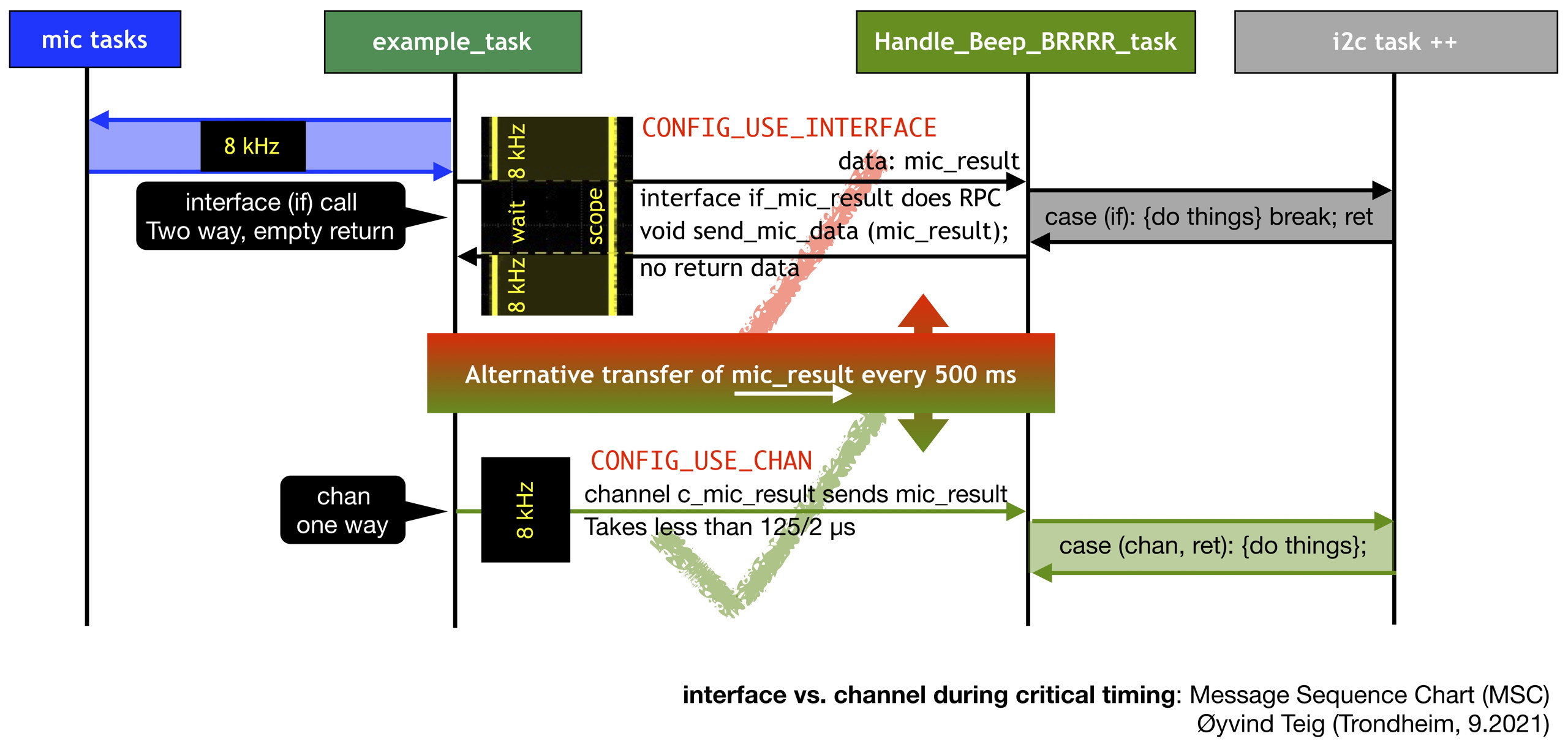
The code basically goes like this. The top code (CONFIG_USE_INTERFACE) in the select accepts the interface call from the example_task, and since Dislay_screen calls I2C serial communication to send a bitmap to the display we see that getting mic samples is halted. This would delay example_task too much. It needs to be back in an 8 kHz rate.
Observe that this is the way an interface call (RPC – Remote procedure call) is supposed to work in xC! This is not a design fault or a compiler error. It makes no difference in the semantics for those calls that do return a value and those that don’t.
I could have decorated with xta timing statements in this code, this would have been more accurate than discovering this by coincidence on the scope. In view of this, I find it rather strange that XMOS is parking xta and even interface calls, in the XTC Tools and lib_xcore.
// In Handle_Beep_BRRRR_task while(1) select case

#if (MY_CONFIG == CONFIG_USE_INTERFACE)

case if_mic_result.send_mic_data (const mic_result_t mic_result) : {
    buttons_context.mic_result = mic_result;

    // BREAKS TIMING, probably because interface returns at the end of the case, and this
    // needs to wait until Display_screen and by it writeToDisplay_i2c_all_buffer

#elif (MY_CONFIG == CONFIG_USE_CHAN)

case c_mic_result :> buttons_context.mic_result : {

// TIMING of example_task not disturbed because the channel input "returns" immediately

#endif
    display_context.state = is_on;
    display_context.screen_timeouts_since_last_button_countdown = NUM_TIMEOUTS_BEFORE_SCREEN_DARK;
    display_context.display_screen_name = SCREEN_MIC;
    Display_screen (display_context, buttons_context, if_i2c_internal_commands);
} break;
The lower config (CONFIG_USE_CHAN) shows the use of a channel instead. Everything is synchronous here, interface calls as well as chan comms. But with the semantics of a chan, only its «rendezvous» time is atomic. When the communication has passed the data across, the sender and the receiver are independent. Therefore this is the method I need to use to move data from the mic tasks to user tasks, so CONFIG_USE_INTERFACE will be removed.
This discussion follows (some moths later) at Decoupling ..task_a and ..task_b.
Min value from mic is constant
 I have decided to count positive
 signed int values as positive dB as and negative values as negative dB and 0 as zero dB. I use 20 * log10 (value) as the basis. Meaning that 1000 or -1000 gives 60 dB and 10000 or -10000 gives 80 dB. Of course, this is not as clean math, see Decibel on Wikipedia. But my usage would look like having two digital VU meters.
20 * log10 (5174375) = 134 dB and -20 * log10 (2147351294) = -186 dB. In maths.xc I have this code:
int32_t int32_dB (const int32_t arg) {

    int32_t ret_dB;

    if (arg == 0) {
        ret_dB = 0; // (by math NaN or Inf)
    } else {
        float dB;
        if (arg > 0) {
            dB =    20 * (log10 ((float)   arg ));
        } else { // if (arg < 0) {
            dB = - (20 * (log10 ((float) -(arg) )));
        }
        ret_dB = (int32_t) dB;
    }

    return ret_dB;
}
I can see that if I make some sounds then the positive dB might become, like 161 dB. But the problem is that the negative value constantly shows the same value 2147351294 (0x7FFDFAFE)! I have not solved this. Update: with 4 mics it’s the positive max that is stuck! See Version v0109
I have set the S_DC_OFFSET_REMOVAL_ENABLED to 1. It runs a single pole high pass IIR filter: Y[n] = Y[n-1] * alpha + x[n] - x[n-1] which mutes DC. See [7] chapter 15. I don’t know if this is even relevant.
Tile[0] rules, what about tile[1]?
My startup code in main.c goes like this:
main.c config code (v0106)
#define INCLUDES
#ifdef INCLUDES
    #include <xs1.h>
    #include <platform.h> // slice
    #include <timer.h>    // delay_milliseconds(200), XS1_TIMER_HZ etc
    #include <stdint.h>   // uint8_t
    #include <stdio.h>    // printf
    #include <string.h>   // memcpy
    #include <xccompat.h> // REFERENCE_PARAM(my_app_ports_t, my_app_ports) -> my_app_ports_t &my_app_ports
    #include <iso646.h>   // not etc.
    #include <i2c.h>

    #include "_version.h" // First this..
    #include "_globals.h" // ..then this

    #include "param.h"
    #include "i2c_client_task.h"
    #include "display_ssd1306.h"
    #include "core_graphics_adafruit_gfx.h"
    #include "_texts_and_constants.h"
    #include "button_press.h"
    #include "pwm_softblinker.h"
#endif

#include "mic_array.h"
#include "AN00220_app_phase_aligned_example.h"

#include "_Beep_BRRR_01.h"

#if (IS_MYTARGET == IS_MYTARGET_MIC_ARRAY)
    //                                                            MIC-ARRAY-1V3-MOD.xc
    on tile[0]: in port p_pdm_clk              = XS1_PORT_1E;  // PORT_PDM_CLK
    on tile[0]: in buffered port:32 p_pdm_mics = XS1_PORT_8B;  // The 8 bit wide port connected to the PDM microphones
                                                               // 7 used: MIC_0_DATA 8B0 to MIC_6_DATA 8B6 (8B7 not connected)
                                                               // Also: "Count of microphones(channels) must be set to a multiple of 4"
                                                               // PORT_PDM_DATA Inputs four chunks of 8 bits into a 32 bits value
    on tile[0]: in port p_mclk                 = XS1_PORT_1F;  // PORT_MCLK_TILE0
    on tile[0]: clock pdmclk                   = XS1_CLKBLK_1; // In "xs1b_user.h" system

    //                                                       MIC-ARRAY-1V3-MOD.xc
    on tile[1]:     port p_i2c             = XS1_PORT_4E; // PORT_I2C             SCL=BIT0, SDA=BIT1
    on tile[1]: out port p_shared_notReset = XS1_PORT_4F; // PORT_SHARED_RESET    BIT0 reset when low
    on tile[1]:     port p_i2s_bclk        = XS1_PORT_1M; // PORT_I2S_BCLK
    on tile[1]:     port p_i2s_lrclk       = XS1_PORT_1N; // PORT_I2S_LRCLK
    on tile[1]:     port p_i2s_dac_data    = XS1_PORT_1P; // PORT_I2S_DAC0

    on tile[0]: out port p_scope_gray       = XS1_PORT_1J; // Mic array expansion header J5, pin 10

    on tile[0]: in buffered port:4 inP_4_buttons = XS1_PORT_4A; // BUTTONS_NUM_CLIENTS
    //
    on tile[0]:     port p_display_scl      = XS1_PORT_1H; // Mic array expansion header J5, pin  3
    on tile[0]:     port p_display_sda      = XS1_PORT_1G; // Mic array expansion header J5, pin  1
    on tile[0]: out port p_display_notReset = XS1_PORT_1A; // Mic array expansion header J5, pin  5 Adafruit 326 v2.1 does not NOT have on-board reset logic
    on tile[0]: out port p_scope_orange     = XS1_PORT_1D; // Mic array expansion header J5, pin  7
    on tile[0]: out port p_scope_violet     = XS1_PORT_1I; // Mic array expansion header J5, pin  9


    on tile[0]: out port leds_00_07 = XS1_PORT_8C;  // BIT0 is LED_0

    on tile[0]: out buffered port:1 led_08 = XS1_PORT_1K;
    on tile[0]: out port led_09            = XS1_PORT_1L;
    on tile[0]: out port led_10            = XS1_PORT_1M;
    on tile[0]: out port led_11            = XS1_PORT_1N;
    on tile[0]: out port led_12            = XS1_PORT_1O;

    // If we need to collect them:
    //out port leds_08_12[NUM_LEDS_08_12] = {XS1_PORT_1K, XS1_PORT_1L, XS1_PORT_1M, XS1_PORT_1N, XS1_PORT_1O};

#endif

#define I2C_DISPLAY_MASTER_SPEED_KBPS  100 // 333 is same speed as used in the aquarium in i2c_client_task.xc,
                                           // i2c_internal_config.clockTicks 300 for older XMOS code struct r_i2c in i2c.h and module_i2c_master
#define I2C_INTERNAL_NUM_CLIENTS 1


#if ((MY_CONFIG == CONFIG_USE_INTERFACE) or (MY_CONFIG == CONFIG_USE_CHAN))
    #if (WARNINGS == 1)
        #warning MY_CONFIG == CONFIG_USE_INTERFACE
    #endif

    int data [NUM_DATA_X] [NUM_DATA_Y];

    int main() {

        interface pin_if_1       if_pin    [BUTTONS_NUM_CLIENTS];
        interface button_if_1    if_button [BUTTONS_NUM_CLIENTS];
        interface pwm_if         if_pwm;
        interface softblinker_if if_softblinker;
        i2c_general_commands_if  if_i2c_general_commands;
        i2c_internal_commands_if if_i2c_internal_commands;
        i2c_master_if            if_i2c[I2C_HARDWARE_NUM_BUSES][I2C_HARDWARE_NUM_CLIENTS];

        #if (MY_CONFIG == CONFIG_USE_INTERFACE)
            mic_result_if      if_mic_result;
            #define MIC_RESULT if_mic_result
            #if (WARNINGS == 1)
                #warning MY_CONFIG == CONFIG_USE_INTERFACE
            #endif
        #elif (MY_CONFIG == CONFIG_USE_CHAN)
            chan               c_mic_result;
            #define MIC_RESULT c_mic_result
            #if (WARNINGS == 1)
                #warning MY_CONFIG == CONFIG_USE_CHAN
            #endif
        #endif

        par {
            on tile[0]:{
                configure_clock_src_divide  (pdmclk, p_mclk, 4);
                configure_port_clock_output (p_pdm_clk, pdmclk);
                configure_in_port           (p_pdm_mics, pdmclk);
                start_clock                 (pdmclk);

                streaming chan c_pdm_to_dec[DECIMATOR_COUNT];
                streaming chan c_ds_ptr_output[DECIMATOR_COUNT]; // chan contains pointers to data and control information
                                                                 // Relies oo shared memory, so both's ends taks must on the same tile as this task
                // mic_array_pdm_rx()
                //     samples up to 8 microphones and filters the data to provide up to eight 384 kHz data streams, split in two streams of four channels.
                //     The gain is corrected so that a maximum signal on the PDM microphone corresponds to a maximum signal on the PCM signal.
                // PDM microphones typically have an initialization delay in the order of about 28ms. They also typically have a DC offset.
                // Both of these will be specified in the datasheet.

                par {
                    mic_array_pdm_rx              (p_pdm_mics, c_pdm_to_dec[0], c_pdm_to_dec[1]);                     // in pdm.xc, calls pdm_rx_asm in pdm_rx.xc which never returns
                    mic_array_decimate_to_pcm_4ch (c_pdm_to_dec[0], c_ds_ptr_output[0], MIC_ARRAY_NO_INTERNAL_CHANS); // asm in decimate_to_pcm_4ch.S
                    mic_array_decimate_to_pcm_4ch (c_pdm_to_dec[1], c_ds_ptr_output[1], MIC_ARRAY_NO_INTERNAL_CHANS); // asm in decimate_to_pcm_4ch.S
                    example_task                  (c_ds_ptr_output, data, p_scope_gray, MIC_RESULT);                  // chan contains ptr to shared data, must be on the same tile
                                                                                                                      // as mic_array_decimate_to_pcm_4ch
                }
            }

            par {
                on tile[0]: Handle_Beep_BRRRR_task (
                        if_button, leds_00_07, if_softblinker,
                        if_i2c_internal_commands,
                        if_i2c_general_commands,
                        p_display_notReset,
                        MIC_RESULT);

                // Having this here, and not in combined part below, avoids "line 2303" compiler crash:
                on tile[0].core[0]: I2C_Client_Task_simpler (if_i2c_internal_commands, if_i2c_general_commands, if_i2c);
            }

            on tile[0]: { // Having these share a core avoids "line 183" compiler crash and runs:
                [[combine]]
                par {
                    softblinker_task (if_pwm, if_softblinker);
                    pwm_for_LED_task (if_pwm, led_08);
                    i2c_master (if_i2c[I2C_HARDWARE_IOF_DISPLAY_AND_IO], I2C_HARDWARE_NUM_CLIENTS, p_display_scl, p_display_sda, I2C_DISPLAY_MASTER_SPEED_KBPS); // Synchronous==distributable
                }
            }

            on tile[0]: {
                [[combine]]
                par {
                    Buttons_demux_task (inP_4_buttons, if_pin);
                    Button_task        (IOF_BUTTON_LEFT,      if_pin[IOF_BUTTON_LEFT],      if_button[IOF_BUTTON_LEFT]);      // BUTTON_A
                    Button_task        (IOF_BUTTON_CENTER,    if_pin[IOF_BUTTON_CENTER],    if_button[IOF_BUTTON_CENTER]);    // BUTTON_B
                    Button_task        (IOF_BUTTON_RIGHT,     if_pin[IOF_BUTTON_RIGHT],     if_button[IOF_BUTTON_RIGHT]);     // BUTTON_C
                    Button_task        (IOF_BUTTON_FAR_RIGHT, if_pin[IOF_BUTTON_FAR_RIGHT], if_button[IOF_BUTTON_FAR_RIGHT]); // BUTTON_D
                }
            }
        }
        return 0;
    }
#else
    #error no config
#endif
Read less…
tile[0]! Plus, the mics are connected to the same tile. So I have no code on tile[1] – which gives the system a major slant towards tile[0]. I guess I need to make some multplexer task to make it possible to have my data processing code code on tile[1]. Stay tuned. I will.
Version 0109
This version decimates 4 mics instead of 8. The very strange thing is that this time it’s the negative max value (= min value) that changes, while it’s the most positive value that is constant. But at a different value than the for the negative, which for v0106 was 2147351294 (0x7FFDFAFE). The stuck positive max this time is 670763580 (0x27FB0A3C). What is happening here?
Download 0109
This download may be considered intermediate.
- See Download code – (500 kB) no
.buildor/bin, but.git
Log B
- I am trying to get acquainted with the code and documentation (and my requirements, looking at sound files and their FFT (Fast Fourier Transform) spectrum/spectra), and found this piece of code: 141:[Ordered select combined with default case]
lib_i2c and AN00219
Problems with I2C and DAC(?)
Download of the AN00219_app_lores_DAS_fixed code.
I had problems with getting the appnote AN00219_app_lores_DAS_fixed (above) to always run correctly. The input mics always worked (the center LED lit up), but the headset did not always get streamed DAC values to them. This is a perfect demo to learn about the workings of the board. But it’s not for newbies, with little comments, and it’s obvious that the programmer has not read his Code Complete (by Steve McConnell). (And.., but probably not relevant here (because I meant coding style, I have no idea how programmers fare inside XMOS): The Clean Coder: A Code of Conduct for Professional Programmers (by Robert Martin)). I wish XMOS would have taken their appnote programmers to a course, at least the ones that have coded all the appnotes and libraries I have had any close encounter with. The deep knowledge of the xCore architecture of the programmers always shine through, but also their Code unComplete. Plus, the appnotes could have been updated more..
This demo comes with the MIC-ARRAY-1V0.xn config file which at first seemed to be the only one that worked. However, it did have a problem with compiling the PORT_LED_OEN signal being init to null. On HW 2V0 of mic array board it is tied to ground, and there’s no port output to control it. So I removed it and modified in lib_mic_array_board_support.h in that library:
lib_mic_array_board_support.h mods
#if defined(PORT_LED_OEN)
    #define MIC_BOARD_SUPPORT_LED_PORTS {PORT_LED0_TO_7, PORT_LED8, PORT_LED9, PORT_LED10_TO_12, PORT_LED_OEN}
    /** Structure to describe the LED ports*/
    typedef struct {
        out port p_led0to7;     /**<LED 0 to 7.    P8C              */
        out port p_led8;        /**<LED 8.         P1K              */
        out port p_led9;        /**<LED 9.         P1L              */
        out port p_led10to12;   /**<LED 10 to 12.  P8D 0,1,2        */
        out port p_leds_oen;    /**<LED Output enable (active low). */
    } mabs_led_ports_t;
#else // Mic array board 2V0
    #define MIC_BOARD_SUPPORT_LED_PORTS {PORT_LED0_TO_7, PORT_LED8, PORT_LED9, PORT_LED10_TO_12}
    /** Structure to describe the LED ports*/
    typedef struct {
        out port p_led0to7;     /**<LED 0 to 7.   P8C       */
        out port p_led8;        /**<LED 8.        P1K       */
        out port p_led9;        /**<LED 9.        P1L       */
        out port p_led10to12;   /**<LED 10 to 12. P8D 0,1,2 */
    } mabs_led_ports_t;
#endif
I then saw that the lib_mic_array_board_support had an .xn config file by itself, which I removed. Since the compiler would not allow the same name of these config files, I did not like having two. I have no idea how the compiler (or mapper) might treat already defined values.
But I still experienced problems, much like those described in Microphone array AN00219 no sound (below). The lib_12c that was required was >=4.0.0. Observe that even if I have had no no-runs with the below fix, I am not certain that this is the fix. I measured the I2C traffic on the scope. It’s doing all I2C just after DAC_RST_N has gone high (it’s low by pull-down R71 and high impedance output after power up) – to initialise the PLL and the DAC at that phase. It worked, but then, on the «next» debug, it didn’t. But then, when I had all the tiny wires soldered onto I2C_SCL (TP18) and I2C_SDA (TP17) and on R71 and connected to my three inputs on the scope, I seemed to experience that it worked on every(?) debug session. I could hear myself typing away in the headphones every time. From experience then a yellow light lits. Timing problem? Observe that the mic input always worked, the center LED was blinking.
 According to the I2C spec (Wiki-refs) chapter «Timing diagram» the
 SDA signal should never change while SCL is high. But what are the margins? The I2C speed is set to 100 kHz. On the mic array board the SDA and SCL lines are shared on the same port and this is solved in i2c_master_single_port. On all my other boxes (and this one, for that matter – for the display) I have used one bit ports for both SDA and SCL, which is «easier». But some times they are scarce, so using two bits of a vacant 4 bit port will work on X2 processors.
Since loading with the scope probes seemed to change matters, I downloaded lib_i2c 5.0.0. By scoping the same lines, the SCL low to SDA low went from 116 ns to 560 ns (see inset). I haven’t inspected the code to see whether this is even possible, the code may be the same. However, the code in i2c_master_single_port.xc differ so much that diff is just as confused as I am. There might be subtle differences that would account for the longer 116 vs. 560 ns timing. Having a short glimpse at the data sheet of the Cirrus Logic chips CS2100-CP PLL [12] and CS43L21 DAC [13] reveals some points that could point towards 116 ns being less repeatable than 560 ns, and may also describe why the scope probes seemed to help:
- SDA Setup time to SCL Rising tsud is min = 250 ns
- SDA Hold Time from SCL Falling («Data must be held for sufficient time to bridge the transition time, tf, of SCL») thdd = 0 µs
The first thing I had done when I suspected the I2C was to print out all the I2C returns i2c_regop_res_t at the init section of i2s_handler. They were all I2C_REGOP_SUCCESS, even with i2c_lib 4.0.0. But then, there is no parity or CRC checks here, and what would still be open would be single bit errors in the data, even if the start and stop conditions were successful.
✓ I guess that the conclusion must be that if I had downloaded lib_i2c 5.0.0 initially then I would have saved some time! Anyhow, I did learn a thing or two..
Output a sine
I also added an option to output a sine, as suggested my mon2 in Microphone array AN00219 no sound. But it did not work when adding code in the i2s.send callback in the i2s_handler. You’d have to figure out some by yourself:
sine output code
#if (TEST_SINE_480HZ==1)
    #define SINE_TABLE_SIZE 100 // 48 kHz / 100 = 480 Hz
    const int32_t sine_table[SINE_TABLE_SIZE] = // Complete sine
    {
        0x0100da00,0x0200b000,0x02fe8100,0x03f94b00,0x04f01100,
        0x05e1da00,0x06cdb200,0x07b2aa00,0x088fdb00,0x09646600,
        0x0a2f7400,0x0af03700,0x0ba5ed00,0x0c4fde00,0x0ced5f00,
        0x0d7dd100,0x0e00a100,0x0e754b00,0x0edb5a00,0x0f326700,
        0x0f7a1800,0x0fb22700,0x0fda5b00,0x0ff28a00,0x0ffa9c00,
        0x0ff28a00,0x0fda5b00,0x0fb22700,0x0f7a1800,0x0f326700,
        0x0edb5a00,0x0e754b00,0x0e00a100,0x0d7dd100,0x0ced5f00,
        0x0c4fde00,0x0ba5ed00,0x0af03700,0x0a2f7400,0x09646600,
        0x088fdb00,0x07b2aa00,0x06cdb200,0x05e1da00,0x04f01100,
        0x03f94b00,0x02fe8100,0x0200b000,0x0100da00,0x00000000,
        0xfeff2600,0xfdff5000,0xfd017f00,0xfc06b500,0xfb0fef00,
        0xfa1e2600,0xf9324e00,0xf84d5600,0xf7702500,0xf69b9a00,
        0xf5d08c00,0xf50fc900,0xf45a1300,0xf3b02200,0xf312a100,
        0xf2822f00,0xf1ff5f00,0xf18ab500,0xf124a600,0xf0cd9900,
        0xf085e800,0xf04dd900,0xf025a500,0xf00d7600,0xf0056400,
        0xf00d7600,0xf025a500,0xf04dd900,0xf085e800,0xf0cd9900,
        0xf124a600,0xf18ab500,0xf1ff5f00,0xf2822f00,0xf312a100,
        0xf3b02200,0xf45a1300,0xf50fc900,0xf5d08c00,0xf69b9a00,
        0xf7702500,0xf84d5600,0xf9324e00,0xfa1e2600,0xfb0fef00,
        0xfc06b500,0xfd017f00,0xfdff5000,0xfeff2600,0x00000000,
    };
#endif

void lores_DAS_fixed (
    streaming chanend c_ds_output[DECIMATOR_COUNT],
    client interface  mabs_led_button_if lb,
    chanend           c_audio) {

    #if (TEST_SINE_480HZ==1)
      size_t iof_sine = 0;
    #endif
    unsafe {
        while(1) {
            select {}

            int output = 0;
            #if (TEST_SINE_480HZ==0)
                for (unsigned i=0;i<7;i++)
                    output += (delay_buffer[(delay_head - delay[i])%MAX_DELAY][i]>>3);
            #elif (TEST_SINE_480HZ==1)
                output = sine_table[iof_sine];
                iof_sine = (iof_sine + 1 ) % SINE_TABLE_SIZE;
            #else
                #error
            #endif
            output = ((int64_t)output * (int64_t)gain)>>16;

            // Update the center LED with a volume indicator
            unsigned value = output >> 20;
            unsigned magnitude = (value * value) >> 8;

            lb.set_led_brightness (12, magnitude); // The frequency is in there and
                                                   // not related to anything here!

            c_audio <: output;
            c_audio <: output;

            delay_head++;
            delay_head%=MAX_DELAY;
        }
    }
}
- 480 Hz output → 2.083 ms per period → 20.83 µs for each of the 100 samples in the sine
- DECIMATION_FACTOR 2 // Corresponds to a 48 kHz output sample rate → 20.83 µs
- Or simply 48 kHz / 100 = 0.48 kHz = 480 Hz
I also saw that the max output was about 1.9V peak-peak when the gain value was 500953, but it did vary on gain going up or down, and it did have some hysteresis. When out of range the signal sounded terrible and looked terrible on the scope. I guess that’s what happens when audio samples wrap around into the DAC.
Version v0200
I have started to merge some of my edited to be more code complete‘ed from AN00219 into my own code. I am planning to do some mere merging so that I can output to the headset. I just assume that would be nice. The 180 Hz sine sine comes from the Online Tone Generator.This code uses these libraries, even if there is no i2s and i2c code for the DAC and PLL yet. I’ll port that from AN00219 for the next version. I’ll come back with analysing the timing here.
Using build modules:
lib_i2c(5.0.0)
lib_logging(2.1.0)
lib_xassert(3.0.0)
lib_mic_array(3.0.1)
lib_i2s(2.2.0)
lib_mic_array_board_support(2.2.0) l
ib_dsp(3.1.0)
With this code, the problem with the dB values seem ok. Both the negative values and the positive values would show the same dB, none is stuck to some value.
xSCOPE v0200

Fig.6 – Beep-BRRR version 2.0.0 with XScope and 180 Hz sine
USE_XSCOPE=1 from makefile is picked up in _globals.h and the function Handle_mic_data in AN00220_app_phase_aligned_example.xc does a:
mic_array_word_t sample = audio[iof_buffer].data[IOF_MIC_0][iof_frame];
XSCOPE_INT (VALUE, sample);
for every sample from mic_0. This is how xTIMEcomposer gets the values. It’s also possible to switch this on and off in the debug configuration with XScope modes Disabled, Off-line or Real-time mode. Anyhow, for my scheme to work it cannot be disabled.
More at xSCOPE (below).
Download v0200
This code is also very intermediate, but it’s a step forward.
See Download code – (625 kB) no .build or /bin, but .git
Version v0218
In this I have changed the buttons to set the dB sound level of the headset. I have used quite some time to get this right, and understand that the format of gain was something I have called sfix16_t. See file maths_fix16.h. I decided not to use any of the types as defined in lib_dsp or import the advanced libfixmath. I guess this explains most of the pain now solved, with fixed point calculations: (update 13Jan2022: TODO the below cannot be 100% correct):
#define FIX16_UNITY_BITPOS 16                      // # sign bit if signed int
#define FIX16_UNITY        (1<<FIX16_UNITY_BITPOS) // 1.0000 (65565)
#define FIX16_NEG_UNITY    (-1)                    // 11111111 all 1 as 2's complement

typedef uint32_t ufix16_t;
typedef int32_t  sfix16_t;
My problem was to understand the scaling of the AN00219 app. When you see this you will of course understand that if gain is 65536 (1<<16) then the gain is 1.00 and if it’s 32768 (1<<15) the gain is 0.5 which is about the half or 6dB (decibel) down:
output = ((int64_t)output * (int64_t)gain)>>16;
Simple enough, but I did have to repeat all my experience from the years when I did do FFTs in assembler and MPP Pascal in the eighties. (Aside: For the Autronica GL-90 fluid level radar based instrument that we did install a lot of on tank ships (tankers, tank-ships)). Here is the code I ended up with in my code in file mics_in_headset_out.xc:
typedef ufix16_t headset_gain_t;

#define _HEADSET_GAIN_UNITY_BITPOS FIX16_UNITY_BITPOS
#define _HEADSET_GAIN_UNITY        (1 << _HEADSET_GAIN_UNITY_BITPOS)
#define HEADSET_GAIN_DEFAULT       _HEADSET_GAIN_UNITY

headset_gain_t headset_gain  = HEADSET_GAIN_DEFAULT; // change with buttons
int            output_to_dac = 0;

// ...

// Avoids divide/division
// Avoids dsp_math_divide from lib_dsp, since the xCORE-200 will not divide in one instruction
//
output_to_dac =
    (int) ((((int64_t) output_to_dac * (int64_t) headset_gain)) >> _HEADSET_GAIN_UNITY_BITPOS);
With that many layers of definitions, the gain is that I understand it again. And not going all the way from the top level ufix16_t to headset in one jump, I introduced the headset gain level, which is rather fair if you ask me. Plus, I do fancy explicit (value (or type)) conversions even if I see so many parentheses (plural of parenthesis) added.
ch_ab_bidir
This channel sends bidirectionally between ..task_a (as master) and ..task_b (as slave). This is possible (141:[Using a chanend in both directions]). I have chosen to set the channel contents up as struct with a union. In other words, the menu items like headset_gain in menu_result piggy backs on the (possibly) faster mic_result. This is because sending spontaneously in each direction is not possible without fast getting deadly embraced in a deadlock. (The interface pattern client/server with master/slave would cannot deadlock).
typedef struct {
    ab_src_e source;
    union {
        mic_result_t  mic_result;  // spontaneous message: source is task_a
        menu_result_t menu_result; // required response:   source is task_b
    } data;
} ch_ab_bidir_t;

while(1) in mics_in_headset_out_task_a
    mic_array_get_next_time_domain_frame // synchs on sample frequency
        // handle
        ch_headset_out <: ab_bidir_context
        // handle
        ch_ab_bidir :> ab_bidir_context;
        // handle

while(1) in Handle_Beep_BRRRR_task_b
    select
        // ....
        case ch_ab_bidir :> ab_bidir_context
            // handle
            ch_ab_bidir <: ab_bidir_context;
            // handle
How many samples out of decimation per time?
The value of MIC_ARRAY_MAX_FRAME_SIZE_LOG2 in mic_array_conf.h, used by lib_mic_array in decimate_to_pcm_4ch.S (asm), mic_array_frame.h and pdm_rx.S (asm) tells how many samples per microphone that my mics_in_headset_out.xc is receiving per mic_array_get_next_time_domain_frame loop. Here are some examples (I have removed the C comment field, that makes the text more readable):
      # MIC_ARRAY_MAX_FRAME_SIZE_LOG2
2 exp(0)  =    1 sample  per microphone in audio.data in example (AN00219)
2 exp(1)  =    2 samples per microphone in audio.data in example
2 exp(2)  =    4 samples per microphone in audio.data in example
2 exp(3)  =    8 samples per microphone in audio.data in example (AN00220)
...
2 exp(13) = 8192 samples per microphone in audio.data in example
I can compile with code for either 0 or 3 for 1 or 8 samples with -DAPPLICATION_NOTE=219 or 220 in makefile, even if I for the headset only have tested with 219.
My problem is how to move on. I am going to do an FFT of some hundred ms of data. Should I collect the data by getting as many of them as possible from the decimators, and process some place in the mic_array_get_next_time_domain_frame loop, or should I send the data sample-by-sample to a background process that could run on another core to do this?
Of course, the sampling frequency is a factor here. I added this to mic_array_conf.h, which shows the range:
From the PDF doc XM010267
48 kHz, 24 kHz, 16 kHz, 12 kHz and 8 kHz output sample rate by default (3.072MHz PDM clock)
Configurable frame size from 1 sample to 8192 samples plus 50% overlapping frames option,
chapter 11 "Four Channel Decimator"

96 kHz divided by 2, 4, 6, 8 or 12. See "fir_coefs.h" and "fir_coefs.xc" in lib_mic_array
#if (DECIMATION_FACTOR == 2)
    #define COEF_ARRAYS           g_third_stage_div_2_fir  // [126]
    #define SAMPLING_FREQUENCY_HZ 48000                    // 48 kHz
    #define FIR_GAIN_COMPENSATION FIR_COMPENSATOR_DIV_2
#elif (DECIMATION_FACTOR == 4)
    #define COEF_ARRAYS           g_third_stage_div_4_fir  // [252]
    #define SAMPLING_FREQUENCY_HZ 24000                    // 24 kHz
    #define FIR_GAIN_COMPENSATION FIR_COMPENSATOR_DIV_4
#elif (DECIMATION_FACTOR == 6)
    #define COEF_ARRAYS           g_third_stage_div_6_fir  // [378]
    #define SAMPLING_FREQUENCY_HZ 16000                    // 16 kHz
    #define FIR_GAIN_COMPENSATION FIR_COMPENSATOR_DIV_6
#elif (DECIMATION_FACTOR == 8)
    #define COEF_ARRAYS           g_third_stage_div_8_fir  // [504]
    #define SAMPLING_FREQUENCY_HZ 12000                    // 12 kHz
    #define FIR_GAIN_COMPENSATION FIR_COMPENSATOR_DIV_8
#elif (DECIMATION_FACTOR == 12)
    #define COEF_ARRAYS           g_third_stage_div_12_fir // [756]
    #define SAMPLING_FREQUENCY_HZ 8000                     // 8 kHz
    #define FIR_GAIN_COMPENSATION FIR_COMPENSATOR_DIV_12
#else
    #error
#endif
HZ_PER_BIN v0218
I assume that I could accept 8 kHz. The Nyquist–Shannon sampling theorem then offers me a bandwidth up to 4 kHz. This might be enough for the alarm signals I am going to pick up. For the next version of the .h file I have added this table:
Not used (yet), but nice to have:
#define FRAME_LENGTH_SEC_ ((1/SAMPLING_FREQUENCY_HZ) * MIC_ARRAY_NUM_SAMPLES)    // Time per sample * num samples
                                                                                 // Rewrite and multiply by 1000:
#define FRAME_LENGTH_MS   ((1000 * MIC_ARRAY_NUM_SAMPLES)/SAMPLING_FREQUENCY_HZ) // --"--

// NUM_SAMPLES SAMPLING_FREQ_HZ FRAME_LENGTH_MS NUM_FFT_FREQ_BINS HZ_PER_BIN
// 8192         8000            1024            4096              1.95
// 8192        12000            682.666..       4096              2.92
// 4096         8000            512             2048              3.91
// 4096        12000            341.333..       2048              5.86
// 2048         8000            256             1024              7.81
// 2048        12000            170.666..       1024             11.72
I assume that detecting an alarm would need at least 170 ms of the time sequence.
The alternative is to pick out sample-by-sample of some given sample time, put them in an array of «any» length, bit reverse the sequence indices and run the FFT, and then correlate it with some given frequency response(s) of the alarm(s) I’m going to detect. This would also save me memory, since I don’t have to waste it on the N-1 mics I’m not going to use. I have to set up minimum 4 mics because that’s how the decimator works, but with a 1 sample loop this instead only adds up to 4 samples which I collect only one of. With 8192 samples and 4 mics I need 32K words. I’d save at least 24K words.
To get all of this right, there’s a nice reference in «What is the relation between FFT length and frequency resolution?» [16]. (Update: I added the «BIN» columns above after I read this). When I need it for real I’ll have a second and some third looks. Plus, look in my textbook from the extra course I took in the eighties (or a newer one).
However, doing it sample-by-sample, I will miss out on the fact that the decimator can deliver any full sequence in an index bit-reversed manner. I would also miss out on the FIR filter (Finite Impulse response) that the decimators may do for me. But then.. If I am going to use the headset DAC output, I guess that alone will force me to do it sample-by-sample. I can’t really have a long delay, and I can’t have the samples bit reversed!
In the sample-by-sample case I would need to rely on lib_dsp to run dsp_adaptive_nlms (for the FIR) (if some windowing function of the signal in the frequency domain after the FFT won’t do the filtering good enough for me). The library lib_dsp can also be given time sequence samples directly using dsp_fft_bit_reverse. So sample-by-sample isn’t scary at all!
In other words, how often should I send from ..task_a to ..task_b and how much should I send each time? Plus, do I need an intermediate task to decouple the two tasks?
There is more conclusive stuff at HZ_PER_BIN v0705.
Download v0218
See Download code – (1.3 MB) no .build but /bin and .git
Decoupling ..task_a and ..task_b
With less water having flown in this project, I did discuss this also at Chan or interface when critical timing. In other words, I earlier decided not to use interface, partly because it’s not supported in the XTC Tools and lib_xcore. After all, this is going to be new code that I may want to port in the future.
Observe this limitation, however: 141:[[[combine]] and [[combinable]]] where I have described that:
Observe that these are synonymous terms:
channels cannot be used between combined or distributed tasks == channels cannot be used between tasks on the same core, since combined or distributable tasks indeed may run on the same core.
Specification
..task_a(mics_in_headset_out_task_awhich picks up microphone data at sampling rate speeds) cannot be blocked longer than the sampling period since I don’t think the sampling sw «likes» it (hard real-time requirements), plus I wouldn’t like that the unit should have any period where it would not listen for the Beep (alarms of different sorts)- ..
task_b(Handle_Beep_BRRRR_task_b) will some times be busy handling buttons (although, that should probably be ok) – but it shall also write to the display via I2C – quite time consuming. I2C is done in[[combined]]and[[distributed]]tasks. Plus, if I decide to pass over sample per sample, all the DSP handling (like FFT) will be done in that task as well, or at least administered by that task - In other words, the display shall be able to be updated and not disturb the mic sampling. This is not like exactly in the Chan or interface when critical timing chapter, where the display basically was updated after a new mics data set
Implementation

Fig.7 – Decoupling of ..task_a and ..task_b – five alternatives – at least the 6th version (PDF)
For A-C I am not to using streaming chan simply because it won’t decouple by more than an extra sample. At least, this is not going to be my first try, even if it only implies adding streaming to the chan and chanend. It does not have any specific capacity – and streaming chan generally does not solve more than what they are designed for. That being said, implementation C became much simpler when I could remove task_z for a streaming chan, since task_z only purpose is to decouple – ending up in implementation E. The same for A ending up in F. In other words, the reasoning starting this paragraph I guess more reflects my experience with not having such a channel. In the CSP-based runtime systems we implemented at work I always just had the asynchronous channel as not containing any data, kind of like an interrupt or signal only (here). Looking it over, I guess my whole struggle with the A-E list suggests this.
Observe that there are streaming chan in my code already, taken from AN00219 and AN00220 (c_pdm_to_dec and chan_ds_ptr_output). See 141:[Synchronous, or asynchronous with streaming or buffered]
Observe that the «callback» scheme that my code (from AN00219 and AN00220) now uses I cannot use here, since what it does is to introduce synchronization on a not-polling basis. Search for i2c_callback_if and i2s_callback_if. Nice, but it’s this I don’t want here.
Implementation A is what I want to go away from, by spec.
Implementation B implies polling on ..task_a. This could be ok, though.
Implementation C is the more complex, but there is no polling. But maybe it needs too many channels and too many cores. I am not certain on how it would work as [[combinable]] tasks, if the comms between Buffer and Decoupler were done with interface calls (which I have decided not to do, but I still think that would be me first try). This overflow buffer pattern comes from the occam world, where what to do when overflowing is also in full control of the programmer. This is the solution that perhaps is closest to the semantics of the classical bounded buffer (or bounded-buffer) (or even first in, first out FIFO buffer), without using semaphores (Wikipedia: Producer-consumer problem).
Implementation D. See below (here).
Implementation E. A simplification of implementation C with the introduction of a streaming chan. I was so sure that I should go for it when I couldn’t fall asleep on the night of that decision thinking why on the earth bother with the extra task_y? Why not just drop it and go for F?
Implementation F. A simplification of implementation A and E with the introduction of a streaming chan. See even further below (here).
Implementation D («knock-come»)
 This is a pattern that I years ago called «knock-come«. I have, with Promela, formally verified it to be deadlock free, see 009:[The «knock-come» deadlock free pattern]. This solution is not possible without the non-blocking
 streaming chan which the slave uses to tell that it has some data it wants to get rid of, and then immediately go on with its next activity. It will do this only once per sequence, so it will never block on this channel (any buffered channel will also block when it’s full, this would of course have needed to be dealt with. If one have control of producer’s max filling rate and consumer’s minimum emptying rate and scale the channe’sl capacity accordingly, fine. And if there is a surprise then quite a lot of embedded systems (with less than unbounded buffer capacity) have traditionally just crashed and restarted. Don’t run that car or fly in that plane. This is why designing with synchronous channels as the basic tool is easier to get always right. Observe that on overflow it’s then also easier to have control of if, when and what data to discard.). The figure has two types of arrows, one no blocking / immediate handling and one blocking / waiting possible. Observe that this blocking is not pathologic, not any bad semantics, nothing wrong, this is the way CSP (Communicating Sequential Processes, see Wiki-refs) is meant to be from day one. In CSP a channel communication simply is a mutually shared state that tasks synchronize on. I have a full note about this at Not so blocking after all. For xC, from 141:[1] we read:
«Channels provide the simplest method of communication between tasks; they allow synchronous passing of untyped data between tasks. Streaming channels allow asynchronous communication between tasks; they exploit any buffering in the communication fabric of the hardware to provide a simple short-length FIFO between tasks. The amount of buffering is hardware dependent but is typically one or two words of data.»
Observe that even if this pattern of course goes in any direction (left-right as master-slave or slave-master), in this case it’s only the shown roles that would work. It is ..task_b which has the potential to destroy for the time critical ..task_a, which then has to pay the price of doing the «knock«, wait for the «come» (and in the meantime may have to buffer any audio frames that might appear in the meantime) and then block-free send «data» over to the right. Since xC does not have occam’s counted array or variant protocols, ..task_a would need to send twice. First the size, then the data. In other words, there would be four comms between the slave and the master to get the data from slave to master. Master to slave requires only one comm. The good thing is that xCore and xC does all this with little overhead.
AN00219 and AN00220 have while (1) mic_array_get_next_time_domain_framein an endless loop. I need to be able to use a select with the channel from ..task_b as the other component.
The complexity of mic_array_get_next_time_domain_frame is such that wrapping it into a select is perhaps meaningless. I could put the first channel input in a select (schkct: «Checks for a control token of a given value on a streaming channel end. If the next byte in the channel is a control token which matches the expected value then it is input and discarded, otherwise an exception is raised»):
for(unsigned i=0;i<decimator_count;i++)
    schkct(c_from_decimator[i], 8);
But calling f mic_array_get_next_time_domain_frame has timing requirements, and I don’t know it checking that control token can be done from a select.
Alternatively into a timerafter with zero delay. I did test this, and it seems to work.
I have queried about this at xCore Exchange forum (3).
Update 7Dec2021: I have now implemented the knock-come pattern. It seems like the atomic time interval spent in the slave, in a case of the select as mentioned above, with one return sending to the master and some calculations, seem to use 16-162 10 ns clock cycles = 160 ns to 1.6 µs. This is unbelievably fast. I cannot explain the range: [[TODO]]. I also must use [[ordered]] with this select, if not the come is never served. I cannot explain that either: [[TODO]].

Fig.9
Update 14Dec2021: With the 48 kHz output sample rate (T=20.83 µs) I see that if I do no DAC calculation and output to the headset, all the calculations and the complete knock-come takes 3.0 µs.
Press picture to see three scope screens. One is just after init with DAC on, the middle is standard with no DAC and the lower is standard with DAC again.
Observe the difference between the first and the last. This used to be much larger, the DAC outputs took much longer time before I by some stomach feeling added a single DAC output before the while loop. I observer that after a pause in the DAC, and then using it again, its time usage decreased. So I imaged this might have to do with timing. I tried adding delays after the init, but only the extra output helped.
Structure of ..task_a
The structure of ..task_a now goes like this. [[TODO]] I need to find out of this timing, and why a standard output takes two channel outputs. I have queried about this, see point 4 at xCore Exchange forum (below). I tested with one DAC output, and it’s noise only in the headset.
ch_headset_out <: FIX16_UNITY; // "half-write"

tmr :> time_when_samples_ready_ticks;

while (1) {
    [[ordered]]
    select {

        case ch_ab_bidir :> data_ch_ab_bidir : {
            // Handle come-data:
            ch_ab_bidir <: data_ch_ab_bidir;
        } break;

        case tmr when timerafter (timeout_ticks) :> void: {
            mic_array_get_next_time_domain_frame(..);
            // handle
            // Knock (if state allows):
            ch_ba_knock <: data_ch_ba_knock;
            if (headset_gain_off) {
                // Do nothing here
            } else {
                // handle
                ch_headset_out <: output_to_dac;
                ch_headset_out <: output_to_dac;
            }
            // handle timeout_ticks
        } break;
    }
}
Download v0249
See Download code – (1.3 MB) no .build but /bin and .git
The reasons I dropped knock-come

Fig.10. Trying to send 256 samples across breaks timing
Update 22Dec2021: I have decided to drop knock-come and go for Overflow buffer. There are several reasons:
- Since
..task_bis going to do work by its own, not only write to the display over I2C, (I had also planned to do the DSP processing in it), when it will come back and pick up the data from..task_bthere will be «too many» samples that needed to be passed across. In Fig.10 I tested sending 256 samples across and the time critical 48 kHz sampling is broken. For 33 ms (333 kHz I2C writing to the display) not observant time in..task_aI would need 264 samples :#define KC_SAMPLES_BUF_LEN ((SAMPLING_FREQUENCY_HZ * KC_MAX_WAIT_MS) / (1000 * USE_EVERY_N_SAMPLE))and values 48000 * 33 / 1000 * 6 = 264. I could pass over in chunks of 128 which would work, but then: - The problem is that even if I let the basic
mic_array_get_next_time_domain_framehave its 48 kHz (since I haven’t succeeded with the DAC CS43L21 at 8 kHz) and use only 1/6 of those values, I need to «be there» at 20.83 µs (48 kHz) still. This is what is broken, as seen in Fig.10. The headset turns silent, even if only 1/6 of the timings are not met - Even if I manage to run at 8 kHz for both the display and the DAC out, there would be buffering. I would need to handle some kind of FIFO buffer at both ends, in both tasks. The overflow buffer solution basically is a bounded buffer with detection of overflow and I would need to handle only a single FIFO. I have discussed the problems with that solution as well (above), but I have decided to give it a go.
- Plus, the extra select case in
..task_aand knock-come states, I can certainly do without. My next implementation will go back to where it started: one..task_aoutput per sample only. Even if the complexity certainly is moved to the two overflow buffer tasks. A pipe or a bounded buffer aren’t just data! - I can understand why the XMOS solution are channels with shared pointers. However, I am at application level concurrency, sending pointers across is none of my business. Real channels are it. And, they can cross tiles as well!
Download v0255
This is the last version with knock-come. See Download code – (520 KB) no .build and .git but /bin .
Implementation F (“simplest possible”)

Fig.11 – Implementation F is «simplest possible»
It took me having to think through implementations A, B, C, D and E before I saw this implementation. I am hugely naïve on streaming chan, that’s for sure. But I seem to be learning, don’t I? I believe this will work for the following reasons:
..task_awill never block because it will ever send one mic data between each RDY. Astreaming chanbuffers one element (as far as I know), which is just what’s needed in this case. It would have 20.83 µs (48 kHz) to normally get rid of the data- If a RDY has not arrived it would buffer in a FIFO buffer. No problem. This would be rather large, see the
KC_SAMPLES_BUF_LENformula (above). Remember..task_awill be non-responsive when it writes to the display over I2C or does DSP processing - Gain etc from the button pressing and menu system in
..task_bwould be sent down to..task_aon no invitation. It can afford to block since it would never deadlock with..task_asince the other direction is a one-dataset-only per sendingstreaming chan - How a full buffer should be sent «up» there would be two solutions I guess:
- ..Either one sample-by-sample, in which case, for the full speed 48 kHz it would have to catch up all samples before the next major unresponsiveness. I guess this is the critical part
- ..or send all that’s in the buffer when the RDY arrives. For this to happen I need to add length of a next message, so that message may include «all». Provided
streamingbuffers any kind of data. But since C/xC does not allow counted arrays and variant protocols (I miss occam), I may still have to break this up, in like 100 and 100 samples. And then, C does not allow elements of arrays like[data FROM 200 FOR 100](I miss occam 2) I’d have to domemcpyto get this done, one more than necessary, depending how the compiler behaves. I’ll stick to sample-by-sample as a first try. Update 29Dec2021: If..task_asends how many samples are left (like 190), then..task_bmay simply return a number saying how many samples it is waiting for next (like 200), to get both sides to agree on the next sending. The next sending would then be (like 200), where (like 193) are relevant (3 added since last, 7 empty samples). I had to do an extra round for this to work, since astreaming chanonly is non-blocking up for max. 8 bytes

Fig.12 – Implementation F, sending of samples
Fig.12 shows how this version behaves when ..task_b is not listening on the channel for some time. I assume that the two scope screenshots speak for themselves.
Sending over the lost samples (in this version I just send some test values, which I even don’t analyse in ..task_b) is done like in point 6 above. To implement the simple protocol with counted array, which in occam is declared like this:
CHAN OF INT::[]INT packet:
proved to be more complex than I thought.
Update 16Feb2022. I added this text for the next release. When I needed to refresh myself I saw that I hadn’t spelt this out as pseudo-code:
// "IMPLEMENTATION F" IN WORDS:
// REPEAT --------------------------------------------------------------------
//     WHEN task_a has something to send to task_b, either
//        something new
//        something next, or next again, ..
//        something final
//     PHASE1:       task_a will "ping" to task_b to say how much data is left
//                   (max 2 words not to block on asynchronous buffered chan)
//     PHASE2:       task_b eventually sends "ready" to task_a and atomically
//                   goes to wait for response
//                   (task_b may also just send "menu data" any time,
//                   but this is not defined as a "PHASE")
//     PHASE3:       task_a eventually receives the "ready" from task_b and
//                   atomically sends the next batch of max size NUM_MAX_MSG
//                   to task_b (used as synchronous unbuffered chan)
//     CONTINUE_IFF: task_a will repeat (starting a new PHASE1) until it
//                   has sent all SAMPLES_BUF_DIM data
// FINALLY -------------------------------------------------------------------
//     New mic samples that have arrived during this REPEAT
//     are sent in a fast and final PHASE1-PHASE2-PHASE3
// SAMPLES -------------------------------------------------------------------
//     After this one and one sample is sent over inside PHASE1 "pings".
//     PHASE2 is then delayed only if task_b is busy. During that time
//     samples are buffered in task_a until it receives a "ready" from task_b
If you are interested, instead of downloading the full code’s zip, here are the most important files (here):
- mic_array_conf_h.txt – This is needed for the
lib_mic_array - mics_in_headset_out_h.txt – Search for the union of small to longer and longer packets:
ch_ab_all_samples_t; - mics_in_headset_out_xc.txt – Contains
..task_a=mics_in_headset_out_task_a. Search forget_chan_mutual_packet_dim,send_variant_protocol_then_shift_downAnd see how wasmemcpywas to the alternatives) andreceive_variant_protocol - _Beep_BRRR_01_xc.txt – Contains
..task_b=Handle_Beep_BRRRR_task_b. Search forreceive_variant_protocol
I said it was complex, but I finally got it alle spliced together. The scope pictures show it running.
But keep in mind that since I (now, at least), need to get samples at 48 kHz (20.83 µs), then sending over of the buffered data in the packets at 8 kHz rate, I still needed to get it done in much less that 20.83 µs. So there were a lot of scope pictures and versions before I found out how to do it: send max 128 samples at a time (good margin) and use memcpy to shift the buffer down. I did not use a ring buffer, since I think that would not have helped. (Update 13Jan2022: the memcpy usage is wrong in this v0414 version, since I have overlapping segments. It has been fixed in a newer version, coming soon.)
MCLK, DAC and PDM mics SW
fig13_219_xmos_xcore_microphone_array_hardware_manual_about_mclkFig.13 Overview of MCLK, DAC and PDM mics. Derived from XMOS AN00219, view PDF here.
This is meant as an overview for myself, to try to
- Understand what the XMOS AN00219 and AN00220 did
- What I have done with that code (basically names for numbers, or better names for names) plus comments
- Maybe there’s a hidden clue here as to why I can sample the mics at 48 kHz down to 8 kHz, but the DACs for the headset do 48 kHz only. I have tried to discuss this a lot here, but I have also reached out, like at Stack Exchange, Electrical Engineering, point 1 (below)
Download v0414
This is the last version with knock-come. See Download code – (520 KB) no .build and .git but /bin . But some are also listed above.
Version v0437

Fig.14 Task view diagram of v0437 (press picture for PDF)
Fig.14 shows the task diagram, almost like xTIMEcomposer generates it. The export from it is a bad bitmap jpg file, so I drew this in macOS Pages. I guess it speaks for itself. I added some detail, like the Constraint check from xmap. These show how many cores, timers, channels and memory that are used for each tile. (Below, in Task view diagram the most recent architecture is always shown.)
I have done quite a lot of unit testing (or rather task to task testing) on this version. Now sound samples arrive in a correct time series into dsp_task_y. 1024 samples are filled there in 128 ms, since the 48 kHz for the headset DAC output is divided by 6 and every 6th sample is sent away at an 8 kHz pace.
The communication as shown in fig.11 had a serious flaw. The sample that was used to tell «I have got more batch array data» of data_sch_phase1_t (after a button press at which it didn’t get rid of those samples) I had actually used and spliced them into the data set. Since there were older samples not sent away yet, newer samples were interleaved. One for each batch sent, and since I send 90 per batch that would be three wrong samples. To solve this I instead added those samples to the buffer of the sender’s array. Now in the «I have got more batch array data» the sample value there is treated with union:
typedef struct {
    union {
        mic_sample_t mic_sample; // iff chan_mutual_packet_dim == NUM_000
        int32_t      is_void;    // iff chan_mutual_packet_dim >= NUM_001 (MIC_SAMPLE_VOID)
    } valid;
} mic_sample_iff_t;
This caused the algorithm to send typically (for 264 samples collected during the 33 ms time while the receiver could not pick them up since it was busy writing to the display) 90 → 90 → 90 samples. But then, to get rid of the last picked up which also used an is_void sample for the last 90 , with this phase1-2-3 scheme this final value needed to be sent across. So now there are four of these sequences instead of three.
The data path of the samples now looks like this:
tile[0]: mic_array_pdm_rx → mic_array_decimate_to_pcm_4ch → mics_in_headset_out_task_a → Handle_Beep_BRRRR_task_b which only kind of «smells» the data set but sends all of it over to tile[1]: → buffer_task_x → dsp_task_y (more cores vacant there!)
Now I’ll start with the real DSP stuff in dsp_task_y. I will hard code all data for the FFT etc, and then later add a chan up to the GUI (buttons and display) handling in Handle_Beep_BRRRR_task_b.
Download v0437
This is the first version with implementation F and it all working. No application specific DSP code yet. See Download code – (540 KB) no .build and .git but /bin.
Version v0705
See TASK VIEW DIAGRAM. More text to come (14Apr2022).
I have struggled quite a lot with the data range, like Q8_24 and how to relate to it when it comes to my data. From dsp_math in lib_dsp these two types are defined:
typedef int32_t  q8_24;  // [MIN_Q8_24..MAX_Q8_24] (in dsp_math in lib_dsp) =
                         // [-128..127.999999940395355224609375]
typedef uint32_t uq8_24; // [UQ24_MIN..UQ24_MAX] (in my maths_fix.h) =
                         // [0..255.999999]
Observe that dsp_qformat.h has some nice macros, like Q24 or just Q that converts a decimal number into number formats like q8_24. (More: search for Q (number format) Q-format, q_format in this note). I have used this to calculate the dB values, to use the built-in log functions (which is loge or ln) to get the real log value . From my maths_fix.h:
    // log(x) = ln(x) * log(2.71828) = ln(x) * 0.434294481903252
    // 0,434294481903252 * 2exp24 = 7286252,.. = 0x6F2DEC
    #define Q24_LOG10_OF_E_NUM 0x6F2DEC // Becomes 0.434294
    //
    // Same if macros from dsp_qformat.h are used (no runtime added):
    #define Q24_LOG10_OF_E_NUM_ Q24(0.434294) // Becomes 0.434293
    // Alternatively:
    //     #define BP 24   // location of the binary point
    //     Q(BP)(0.434294) // Use
Some of the lib_dsp functions use just two int32_t (re and im), like in dsp_complex_t, while others use a q_format number (like 24), as dsp_math_multiply and dsp_math_multiply_sat do. Since microphone samples are just some kind of int, most of the values are below the decimal point in q8_24. I had to make my own wrappers to follow the data and learn when I had an overflow, like my_dsp_math_multiply_sat.
Observe that to find the magnitude of a complex vector it’s re2 + im2, which very soon overflows. Then taking the sqrt of this also takes som thinking. All this is done in my my_dsp_magnitude, where I have at the moment decided to parameterise if I want to do the proper (?) multiply by N after the FFT, if I want to do magnitude, sqrt and the dB.
The code I now have does dsp_fft_bit_reverse, dsp_fft_forward and then dsp_fft_split_spectrum. There are a lot of comments in my code. I decided that instead of going to the Fixed-Point Representation & Fractional Math kind of stuff that we find in the literature, like [18] where pointers are twisted far beyond my imagination (and the compiler’s imagination, it felt like), I made my own union type. (However [18] second ref. describes the theory behind splitting quite well, press «<<previous» there). There are a lot more comments in _Beep_dsp_handling.h:
typedef struct {
    int64_t dummy_avoid_memory_error_align_below_at_double_word;
    union {
        // ================================================
        // Reuse of buffer, avoids ram usage and memcpy
        // with union instead of complex casts to pointers
        // ================================================
        mic_sample_t  mic_samples   [NUM_MIC_SAMPLES_REAL];     // 1 * 1024
        dsp_complex_t complex_array [NUM_FFT_POINTS_COMPLEX];   // 2 * 512
        dsp_complex_t complex_half_spectra
                      [NUM_FREQ_SPECTRA][NUM_FREQ_POINTS_REAL]; // 2 * 2 * 256
    } u;
} mic_samples_buff_t;
Since xScope turned out to be so difficult I decided to add writing the spectrum to the MikroE DAC 4 board (see [21] plus this described in length around the board layout and KiCad chapters). Another pro about this is that I can see the spectrum in the finished product, if I carry a scope with me. I got this finished about an hour before I decided to actually publish this version as v0705.
I felt I needed a hw port for the scope to control from the logger_task which is on tile[1]. However, all ports on J5 are on tile[0], so I needed a task there to control it. This is port_tile0_task. Also, the I2C crosses the tiles, which ads a lot of data tile crossing. This is done automatically over xConnect, and it’s so fast that it takes «nothing» from the performance.
My external I2C bus also handles the display. In other words, this logging will make the display timing worse, giving a side effect into how many mic samples to store locally in mics_in_headset_out_task_a. I have parameters to set all this, like MAX_WAIT_TIME_TO_SEND_DATA_MS.
Observe that I have not synchronized the usage of this I2C. The display (SSD1306) is written to with its «lots of bytes» intermingled with the «lots of bytes» for the DAC 4 (MCP4728). This is no technical problem, but it would take from the linearity of the spectrum in Fig.21. However, with DO_DISPLAY_SCREEN_OFTEN = 0 this problem would only be seen when I press a button. I have control of any loss of linearity in logger_task. (There is a tiny skew, now removed for the next version).
It’s nice to see the spectrum now with music. But using an Online tone generator or two is also nice. Here is one:

Fig.21 – 977 Hz in full spectrum over 100 ms on the scope, via DAC 4 output CHA. Framed with port 1I
HZ_PER_BIN v0705
From the earlier discussion HZ_PER_BIN v0218 and according to [16] the formula goes like this:
- I collect 1024 samples (
NUM_MIC_SAMPLES) - I then have 1024/2 = 512 FFT bins (
NUM_FFT_POINTS_COMPLEX). Div by 2 isNUM_COMPLEX_PARTS - I sample at 8 kHz (actually I sample at 48 kHz for the headset DAC outputs, but pick out every 6th sample only). This means I have a Nyquist bandwidth of 4 kHz
- My samples represent a snapshot of 1024 * (1/8000) = 128.00 ms
- 4 kHz / 512 FFT bins = 7.81 Hz/bin (
HZ_PER_BIN). This is indeed what I have! - What surprises me somewhat is that the fact that this is correct even if those 1024 original mic samples are treated as two arrays of complex values after the
dsp_fft_forward, done withdsp_fft_split_spectrum. I think [16] tells that this is because the butterflies in the FFT (DSP) it is the resolution of the sine/cosine that is the main param here. My parameter to the FFT is a zero to max sine calleddsp_sine_512which has dim (512/4) + 1 = 129. From this 90° (plus 1 value) curve it’s easy to pick out the other values that are needed, both for sine and cosine - The point in Fig.21 is 977 Hz, which shows up in the display as being at pos [125], seen when I press a button.
977 / 7.81 = 125. The reason why this shows up on the scope as being on the center is that I have framed this inp_scope_violet = XS1_PORT_1Iwhich also envelopes a trigger pulse on DAC 4CHD. I’ll have to make this more concise in the next version - I think going to 2 kHz probably is too little. I need higher resolution, ie. lower
HZ_PER_BIN. In order to double the resolution I would either need to halve the sampling frequency to 4 kHz (which is contrary to what I want since that would only give me 2 kHz bandwidth as a start) or use the double amount of samples (2048 = 256 ms, which could be ok since I’m not after detecting spoken words but rather long beeps). Update 23Apr2022, with version v0800 (not published yet): Oops! I got that one kind of wrong! When I went from 1024 to 2048 samples @ 8 kHz (128 ms to 256 ms) and the two spectra went from 256 to 512 values each, afterdsp_fft_split_spectrum, then HZ_PER_BIN is correctly better by two from 7.81 to 3.905 Hz/bin, but the max frequency of 1999 Hz is moved from the last position [255] to the new last position [511]. So this did not do what I was after - See [22]: for a smoke detector I would need to hear up to 4 kHz.
In Wikipedia’s Smoke detector article it would say «usually about 3200 Hz«. - If I in v0705 increase above some 2 kHz the pulse slides down again. I guess this shows the mirror frequency that may be minimised with a windowing function before the FFT. I queried about this at Stack Exchange’s Digital Processing, point 2 here
Download v0705
See Download code – (629 KB) no .build and .git but /bin.
Version v0711

Fig.22 v0711 992 Hz and piano music (not v0710)
In this version I am able to show both spectra over the 128 ms period on the scope, and it only takes some 40 ms times two. This is done over DAC 4 channel CHA. I synch with 1I (going high at the first spectrum’s start and low at the second spectrum’s start) but also write to DAC 4 channel CHD with a high signal for each curve, low at their ends. This is all done in logger_task.
However, to get this done, I had to rebuild dsp_task_y to become a state machine. This is actually much nicer. In state_get_new_data the 1024 samples are received and all DSP calculations are done to make the spectrum. Actually two spectra, as described in v0705. Then in state_process_spectrum, first with iof_spectrum 0 then 1 (and delivery to the logger_task in between), then the magnitude, sqrt etc. are calculated. I should have built it as a state machine earlier, but then it took only a few hours including testing.
To get this done so fast the nice thing is that the MCP4728 DAC4_REG_FAST_WRITE_COMMAND does not need all the four channels CHA..CHD. Since the data is latched on the I2C ACK after each value, I decided to test this. I did not find this in the data sheet [21]. And it works! I also decided to increase the I2C speed from 333 kHz to the fastest standard speed of 400 kHz (the extra fast is faster). This did not give any errors from the I2C drivers.
Download v0711
See Download code – (631 KB) no .build and .git but /bin.
Version v0805
In this version I have run the following (from file mic_array_conf.h). Which means I always pick up the mic samples at 48 kHz (since the DAC for the headset only allows 48 kHz), but downsample to 16 or 8 kHz for my own processing by just picking out every fourth or sixth. (However, there is more to it than this. The lib_mic_array samples the eight PDMs at ≈ 3.072 MHz and decimates in several double buffered stages, down to two sets of four mics each every 48 kHz. I use the time domain data mic_array_frame_time_domain from the library, not FFT ready data mic_array_frame_fft_preprocessed.) Then, the number of samples I use for the FFT has been tested as 512, 1024 or 2048. The spectra are written to the DAC4, CHA and an output pin does the framing for the scope, as described above.
#define SAMPLING_FREQUENCY_HZ 48000
#define PROCESS_FREQUENCY_HZ  (below) // p-freq
#define NUM_SAMPLES_PER_BATCH (below) // p-num
//
// === SAMPLING ==  ================== FFT =================    ==== SPLITTING IN 2 ====
// p-freq  p-num -> Nyquist-f  FFT-bins  HZ_PER_BIN batch-ms -> spectrum-ms f-max ix-max
//  16000 /  512 ->      8000 /    256 = 31.25            32 ->          16  4000  [127]
//  16000 / 1024 ->      8000 /    512 = 15.625           64 ->          32  4000  [255]
//   8000 / 1024 ->      4000 /    512 =  7.8125         128 ->          64  2000  [255]
//   8000 / 2048 ->      4000 /   1024 =  3.90625        256 ->         128  2000  [511]
These all seem to work fine. I have no other anti-alias filter at the moment than the one which comes with lib_mic_array. See Anti-alias filtering (below).
Here are three of the most important files (as .txt):
- main.xc.txt
- mics_in_headset_out.xc.txt
- _Beep_dsp_handling.xc.txt (some comments updated after v0805)
This version also removes a deadlock that appeared after some update. When I pressed a button, some times some of the tasks froze. I thought it was the writing to the display and some I2C sharing with the logger, but just a delay of 30 ms introduced the race. This problem is named BEEP-005 in the sources. In my experience deadlocks always are seen during rather casual and relaxed testing. I have very few of them, as I have programmed these kind of systems for very many years, and know some of the deadlock free patterns. The classical xC client/server interface pattern is of one of them. But since the next version of the XMOS tool is C + lib_xcore, I try to use as much raw chan as possible. So I stumbled into this. I had commented away some code in buffer_task_x. In dsp_task_y the initial data_sch_knock could not get the result in a select, it had to be immediately below, else possible deadlock. The reason is that i had introduced a state machine, and I gave it new state «in between» comms – causing a potential comms not to happen since the other part also wanted to communicate. Classical deadlock. The most updated, at any time, task view diagram is seen below: TASK VIEW DIAGRAM.
Download v0805
See Download code – (11.1 MB) all included, also .build and .git
Version v0817
With this version I have plugged in two anti-aliasing filters. One is before the downsampling in mics_in_headset_out_task_a and the other is before the FFT in dsp_task_y. See diagram in Signal flow. Also see Stack Exchange, Digital Processing, point 2 and 3, below.
Here are three of the most important files (as .txt):
- main.xc.txt – Observe TASK VIEW DIAGRAM (below)
- mics_in_headset_out.xc.txt – See
dsp_task_y - _Beep_dsp_handling.xc.txt – See
mics_in_headset_out_task_a
Download v0817
See Download code – (735 kB) no .build or .git
Version v0842
Here are some of the changes since v0817, extracted from _version.h:
- I have tried to remove the frames which contain noise from the button presses. This has been more or less successful, partly because the noise appears before the button press or release is detected. However, there is a delay in the build-up of the frames, so I now tag frames at the time when they are processed, whether there has been any detected button press up to then. If I do normal button presses I would not see much of that noise. However, I just need to cross my fingers to hope that my future detection algorithms won’t trigger on that noise
- Parameters for setting the sampling speed etc. have been cleaned up. Now both
NUM_SAMPLES_PER_BATCH512 and 1024 go to 4 kHz by starting at 16 or 8 kHz. I have decided to go for 1024 @ 16 kHz and atPROCESS_FREQUENCY_HZ16000 I now have T 64 ms and 15.625 Hz/bin. Observe that those 64 ms are analysed as two 32 ms bit streams (since I do thisdsp_fft_split_spectrumetc. This has been discussed elsewhere dsp_task_yis now more state based. This made it much easier to understand what was going on. I now have these states:get_new_data_from_x,process_fft_etc,loop_get_ui_data_from_b,loop_process_spectrum,loop_send_to_logger,loop_send_result_to_b,loop_until_analyzelogger_tasknow will now understand if the DAC board is not present. It also is faster, since I only output to one of the DAC channels. One 4 kHz spectrum is output in 26.2 ms – max would be 32 ms. A mechanism to loose spectrum frames tologger_taskhas been made- Each of the two anti-alias filters may now be cascaded.
NUM_SECTIONS_FILTER_Ais 1 andNUM_SECTIONS_FILTER_Yis 2, this allows for cascading anti-alias filters withdsp_filters_biquadsinstead of just onedsp_filters_biquad - Again, some not logical struggle with the xTIMEcomposer 14.4.1, reported to XMOS as reappearing of ticket #183751 XMOS internal number. It just has to be programmed around. I have succeeded with both cases of this rewrite. Made a new file
_global_bug_fix.hto get these cases more exposed - I all of a sudden saw that every other line of the 128 * 64 SSD1306 display was dark, making everything double height. See the picture in Min value from mic is constant and Fig.2. After a day’s work I saw that this display has a different bit placement for each
y(vertical) position. My basis was the Adafruit drivers in C++ for the 128 * 32 display, and I haven’t followed it, and I don’t know how this driver has implemented this code. (But I downloaded just now from Adafruit-GFX-Library and the fileAdafruit_GFX.cppand classGFXcanvas1functiondrawPixelcertainly looks simpler than my solution, and it doesn’t seem to need to differentiate between the two display sizes. But I don’t like that Cpp coding style.. I’ll stick to «my» code.) In my code the function now uses a new array calledy_to_new_ywhich contains the necessary mapping. I started to figure out the algebra, but I soon realised that the math involved did take some cycles more than the table look-up. I made a functionsetPixel_in_buffer_testto understand what was going on. See my new welcome screen at Download code – which has no wasted empty single-pixel lines!
Download v0842
See Download code – (754 kB) no .build or .git
TASK VIEW DIAGRAM
There are many names of task view diagrams. Like process / data flow diagram. I first presented one as Fig.14 Task view diagram (of v0437, above). However, the below diagram will always show the most recent diagram of this real-time embedded software architecture. It’s even hard real time at some places, verified at every build by the xTIMEcomposer’s XTA tool.
fig15_219_task_view_beep_brrr_oyvind_teig Fig.15 – Task view of «newest» version (PDF download here – no bitmap produced)Download code
xC

v0842 welcome screen with no empty pixel-lines, through the scratched box
When this project is finished the code will be downloadable from My xC code downloads page. However, on this page I have the following local intermediate downloads. So download any while it’s still here if you are curious. Observe that I change naming in the code so often that from one version to the next there may be quite some changes, and I like to think that they are improvements that increase my understanding of what I’m doing. If I above have shown code examples related to a particular version, that code is of course not updated. I would probably have jumped right to the newest:
Versions
- Download v0106 (9Sep2021)
- Download v0109 (12Sep2021)
- Download v0200 (20Oct2021)
- Download v0218 (11Nov2021)
- Download v0249 (14Dec2021)
- Download v0249 (21Dec2021) Last version with «knock-come»
- Download v0414 (5Jan2022) First version with «Implementation F». See some of the files right now above
- Download v0437 (26Jan2022)
- Download v0705 (14Apr2022)
- Download v0711 (18Apr2022)
- Download v0805 (26Apr2022) (all included)
- Download v0817 (11May2022)
- Download v0842 (26Jul2022)
Python
- Observe that this download may not be necessary, as using the original XMOS Python 2 file magically runs (on the Python 2 interpreter), even with lots of problems reported! If yo still want my updates, here they are: ../code_python_xmos_lib_mic_array/fir_design_py3.py – 30Apr2022 – Copyright © XMOS! All the results are at ../code_python_xmos_lib_mic_array/fir_design_py3.zip.
KiCad
To appear
Algorithm matters
Update: Maybe start by having a look down at this chapter: Signal flow.
Teaser: dimension 1024 real samples: then dsp_fft_bit_reverse takes 45 µs and dsp_fft_forward 439 µs. This is 43900 cycles for the FFT, doing 4N real multiplications (4096) and 4N-2 real additions (4094) = 8190 operations (taken from the net (here), not counted in dsp_fft_forward. With 10% overhead deducted this is about 4.8 cycles per operation. I don’t yet know if this is correctly observed. This is probably 500-1000 times faster than what we managed to squeeze out of a Texas TMS99105 processor in the eighties. Big disclaimer.
Anti-aliasing filtering
Built into the XMOS decimators
Before you delve into this filter design and how to run the Python file, make sure you really need to modify the parameters for the filter that’s already there from the AN00219 app. It delivers 48 kHz. Since I need that 48 kHz for the headset DAC, in hindsight, I am not certain that I will need to redo this design. But I learnt a lot!
In lib_mic_array user guide ([23], p22) the anti-aliasing done on the data coming out of the decimators is explained. In Stack Exchange, Signal Processing, point 2 (below) the rationale for these filters is explained.
Anti-aliased from decimators
«By default the output signal has been decimated from the original PDM in such a way to introduce no more than -70dB of alias noise (during the decimation process) into the passband for all output sample rates.»
PDM sample rate is 307200 Hz. Since I use DECIMATION_FACTOR 2 then
output_decimation_factor Passband(Hz) Stopband(Hz) Ripple(dB) THD+N(dB)
2                        18240        24000        1.40       -144.63
«The decimation is achieved by applying three poly-phase FIR filters sequentially. The design of these filters can be viewed in the python script fir_design.py.» There is a separate chapter, starting on page 24: fir_design.py usage.
The group delay is 18 output clock cycles. The dynamic range is:
output_decimation_factor Dynamic Range (dB)
2                        156.53
Running fir_design.py
I mentioned above that in ([23], p24) there is a separate chapter, starting on page 24: fir_design.py usage.
However, fir_design.py is written in Python 2.7. This is like the animal pictures on the cave walls, several years old. Freshest in the cave is Python 3.10.
Update: Observe that this Python 2 to 3 rewrite may not be necessary, as using the original XMOS Python 2 file magically runs (on the Python 2 interpreter), even with lots of problems reported!
Python3 with VSCode on macOS Monterey
Since I haven’t had any Python up and running on my machine, I decided to update to the newest version of the macOS (30Apr2022: Monterey 12.3.1). See 059:[macOS 12 Monterey]. – where you would also see why I did this. Too much old stuff, and macOS 10.14 Mojave was out of fashion, around the Python 2.7 stuff.
Also on Monterey I at first tried to install Python and imports in a Terminal window, but soon found out that maybe just drop this and get all the help I can get from Visual Studio Code (VSCode). XMOS suggest this for their next toolset, so I’ll just do it. VSCode seems to be built on top of Terminal windows, but hoped that it would be easier to get things consistent for an amateur like me. It was. Like, I should now install Python in the VSCode Terminal window:
brew install python3
At first I needed to install the Microsoft Python Extension (here). Nice. This was advised from Python in Visual Studio Code. However, it was the «Hello World» example in Getting Started with Python in VS Code that helped me the most.
I then took the fir_design.py from lib_mic_array and moved it into a project called fir_design, and called the file fir_design_py3.py. I at first tried to install scipy alone, but it wasn’t seen. But on SciPy installation I found
python3 -m pip install numpy scipy ipython jupyter
I had already done, from the «Hello World» example:
python3 -m pip install matplotlib
Now I had all needed imports added.
I get a complaint that:
The default interactive shell is now zsh.
To update your account to use zsh, please run `chsh -s /bin/zsh`.
but if I do it I get «No changes made». Maybe because I have done it before. But ignoring this seems so far to be fine.
Also, observe that the virtual environment I installed generates a directory called .venv, which is rather full: 483 MB! To inspect it in macOS: 059:[How to see hidden files in macOS] (when in Finder: Command + Shift + . (Cmd–Shift–dot))
(.venv) mymachine:lib_mic_array teig$ python3 --version
Python 3.10.4
(.venv) mymachine-2016:lib_mic_array teig$
I then needed to select the Python interpreter: via the Command Palette (⇧⌘P):
Python: Select Interpreter
* Python 3.10.4 ('.venv':venv) ./.venv/bin/python Recommended
..
..
Python 2.7.16 64-bit /usr/local/bin/python
I assume that if I had chosen the bottom Python 2.7 I would not have needed to fix the code for Python 3. But I’m kind of tired of being behind. I haven’t tried 2.7 – but assume that all these warnings would then surface. Anyhow, I did go for the newest:
To get the the script run to the end, I needed to fix these problems:
# Teig: 30Apr2022
# This script was originally run as Python 2.7. I now use 3.10, causing several problems
# 1. all print "qwe" now print ("qwe")
# 2. See https://stackoverflow.com/questions/13355816/typeerror-list-indices-must-be-integers-not-float
#   Both of the below solved with int() typecast around divisions
#       TypeError: list indices must be integers or slices, not float
#       TypeError: 'float' object cannot be interpreted as an integer
fir_design_py3.py
This file (fir_design_py3.py) and the results (.h, .xc and several .PDF) may be downloaded from Download code (above). Fast to see: here – Copyright © XMOS! Don’t ask me about it! After all I’m supposed to be a user!?
It generates the below files and log (separate fold). These are described in [23]. I should now be in scope to read that chapter. Stay tuned.
fir_coefs.h		output_div_12.pdf	output_div_8.pdf	third_stage_div_4.pdf
fir_coefs.xc		output_div_2.pdf	second_stage.pdf	third_stage_div_6.pdf
output_div_4.pdf	third_stage_div_12.pdf	third_stage_div_8.pdf
first_stage.pdf		output_div_6.pdf	third_stage_div_2.pdf
fir_design_py3.py log
Filer Configuration:
Input(PDM) sample rate: 3072.0kHz
First Stage
Num taps: 48
Pass bandwidth: 30.0kHz of 1536.0kHz total bandwidth.
Pass bandwidth(normalised): 0.01953125 of Nyquist.
Stop band attenuation: -100.0dB.
Stop bandwidth: 30.0kHz

Second Stage
Num taps: 16
Pass bandwidth: 16kHz of 384.0kHz total bandwidth.
Pass bandwidth(normalised): 0.08333333333333333 of Nyquist.
Stop band attenuation: -70.0dB.
Stop bandwidth: 16kHz

Third Stage
Filter name: div_2
Final stage divider: 2
Output sample rate: 768.0kHz
Pass bandwidth: 291.84000000000003kHz of 384.0kHz total bandwidth.
Pass bandwidth(normalised): 0.76 of Nyquist.
Stop band start: 384.0kHz of 384.0kHz total bandwidth.
Stop band start(normalised): 1.0 of Nyquist.
Stop band attenuation: -70.0dB.
Passband ripple = 1.4044089236034487 dB

Filter name: div_4
Final stage divider: 4
Output sample rate: 384.0kHz
Pass bandwidth: 161.28kHz of 192.0kHz total bandwidth.
Pass bandwidth(normalised): 0.84 of Nyquist.
Stop band start: 199.68kHz of 192.0kHz total bandwidth.
Stop band start(normalised): 1.04 of Nyquist.
Stop band attenuation: -70.0dB.
Passband ripple = 0.49486301668807575 dB

Filter name: div_6
Final stage divider: 6
Output sample rate: 256.0kHz
Pass bandwidth: 107.52kHz of 128.0kHz total bandwidth.
Pass bandwidth(normalised): 0.84 of Nyquist.
Stop band start: 133.12kHz of 128.0kHz total bandwidth.
Stop band start(normalised): 1.04 of Nyquist.
Stop band attenuation: -70.0dB.
Passband ripple = 0.24371331652398948 dB

Filter name: div_8
Final stage divider: 8
Output sample rate: 192.0kHz
Pass bandwidth: 80.64kHz of 96.0kHz total bandwidth.
Pass bandwidth(normalised): 0.84 of Nyquist.
Stop band start: 99.84kHz of 96.0kHz total bandwidth.
Stop band start(normalised): 1.04 of Nyquist.
Stop band attenuation: -70.0dB.
Passband ripple = 0.18294472135805998 dB

Filter name: div_12
Final stage divider: 12
Output sample rate: 128.0kHz
Pass bandwidth: 53.76kHz of 64.0kHz total bandwidth.
Pass bandwidth(normalised): 0.84 of Nyquist.
Stop band start: 66.56kHz of 64.0kHz total bandwidth.
Stop band start(normalised): 1.04 of Nyquist.
Stop band attenuation: -70.0dB.
Passband ripple = 0.12019294827450287 dB
fir_design_py3.py results
I have run a diff of fir_coefs.h and fir_coefs.xc files, and the only difference I see are the dates in the top:
// Copyright (c) 2022, XMOS Ltd, All rights reserved
// Copyright (c) 2016-2017, XMOS Ltd, All rights reserved
However, the PDFs seem to differ from those in [23].
XMOS AN00209, lib_dsp and dsp_design.h
I’m not sure about Audacity or baudline, since what I’m after just now is a low pass filter and/or windowing function before the FFT. I cannot accept that a beep above some 4 kHz just wraps around and comes into the spectrum again! I now have installed AN00209 (above). Plus, I see that dsp_design.h in lib_dsp may generate parameters for me, for later use in the filters proper. Here is an example (it looks to me like the code running inside it is the LPF part of [23]):
void dsp_design_biquad_lowpass
(
    double        filter_frequency, // in, is f0/Fs
    double        filter_Q,         // in
    int32_t       biquad_coeffs[5], // return
    const int32_t q_format          // in
);
The biquad filter is described in Wikipedia at Digital biquad filter.
.svg) Compiling and running the AN00209_app_design I get the following log (below). In it the time sequence of an infinite impulse (the XMOS code says it’s a Dirac delta function, Wikipedia here – but I am confused whether it’s the Kronecker delta they mean, Wikipedia here. Update: I got this answered on Stack Exchange’s Digital Processing forum, point 1 here: it is a Kronecker delta) going through an infinite impulse response (IIR) filter is the sinc function, Wikpedia here (which only seems to hold for the Dirac delta..). (Aside: however, giving the filter a rectangular pulse instead of a nailed delta pulse, then its time series output is the same as its spectrum, ie. as taking that rectangular pulse through the FFT). The figure shows the sinc of a low-pass filter (Wikipedia, figure here).
Compiling and running the AN00209_app_design I get the following log (below). In it the time sequence of an infinite impulse (the XMOS code says it’s a Dirac delta function, Wikipedia here – but I am confused whether it’s the Kronecker delta they mean, Wikipedia here. Update: I got this answered on Stack Exchange’s Digital Processing forum, point 1 here: it is a Kronecker delta) going through an infinite impulse response (IIR) filter is the sinc function, Wikpedia here (which only seems to hold for the Dirac delta..). (Aside: however, giving the filter a rectangular pulse instead of a nailed delta pulse, then its time series output is the same as its spectrum, ie. as taking that rectangular pulse through the FFT). The figure shows the sinc of a low-pass filter (Wikipedia, figure here).
AN00209 app_design
The coefficents are described in [24]. At least dsp_design_biquad_lowpass has been picked from the LPF section there.
In AN00209_app_design different coefficients are passed to the IIR filter dsp_filters_biquad to make it behave as several filter types. I have modified the code to print out the params and coeffs as well (it’s app_design.xc.txt © XMOS. I also fixed some sloppy errors in the original). I have also made the q_format visible, and saw how the last three filters failed at higher Q-formats, see app_design_logs.pdf. Value 3 needs at least 2 bits and value 1 needs at least one bit. If you download that file and use page up/down so that each log aligns with the other, you will see that going from Q-format 28 down to 16 destroys some accuracy of the fractional part only, since there are less resolution in the smallest. The hex values differ (3 is 0x30000000 and 0x00030000), but the values as such are meant to be the same (3). I did some colouring there as well.
As always printed with 8 decimals we’d for the first values have the below list. think that the fewer bits, the larger the quantisation noise of the filter. To minimise noise, higher order filtering (than the biquad second order filter) are made by cascading several using dsp_filters_biquads.
Q-format 16 +0.58573914
Q-format 24 +0.58574975
Q-format 28 +0.58574980
Q-format 29 +0.58574980
Q-format 30 +0.58574980
Q-format 31 +0.58574980
The XMOS default log with Q-format 28 is below (log with my additions in the code). But first this:
From XMOS dsp_filters.h in lib_dsp
Copyright 2015-2021 XMOS LIMITED

dsp_filters_biquad

    This function implements a second order IIR filter (direct form I).

    The function operates on a single sample of input and output data
    (i.e. and each call to the function processes one sample).

    The IIR filter algorithm executes a difference equation on
    current and past input values x and past output values y:

    y[n] = x[n]*b0 + x[n-1]*b1 + x[n-2]*b2 + y[n-1]*-a1 + y[n-2]*-a2
If I need to cascade them for higher order IIR there is the mentioned dsp_filters_biquads available. If offers num_sections sections, adding a degree of two between each section. Actually, the dsp_filters_biquad is a call to dsp_filters_biquads with num_sections = 1.
Doing this cascading then the output “right” part of the one filter may be cloned for the next input “left” section. This will save some cycles. Ref Wikipedia’ Digital biquad filter article, direct form 1 (direct form I) which is the form used here. I haven’t studied whether this applies for this library.
The filters are in lib_dsp coded in xCore assembler, either as inline asm or in .S files.
AN00209 app_design log
XMOS AN00209 app_design, mods by Teig 3May2022

Q_FORMAT 28
Max 3.000000 as FNN +3.00000000 (0x30000000 as QNN 0x30000000)
1   1.000000 as FNN +1.00000000 (0x10000000 as QNN 0x10000000)

                             f_n   Q      gain-dB
dsp_design_biquad_notch     (0.25, 0.707, ..     )
dsp_design_biquad_lowpass   (0.25, 0.707, ..     )
dsp_design_biquad_highpass  (0.25, 0.707, ..     )
dsp_design_biquad_allpass   (0.25, 0.707, ..     )
dsp_design_biquad_bandpass  (0.25, 0.707, ..     )
dsp_design_biquad_peaking   (0.25, 0.707, 3.0, ..)
dsp_design_biquad_lowshelf  (0.25, 0.707, 3.0, ..)
dsp_design_biquad_highshelf (0.25, 0.707, 3.0, ..)

                    b0           b1           b2           -a1          -a2
Coeffs of notch     +0.58574980, +0.00000000, +0.58574980, +0.00000000, -0.17149958
Coeffs of lowpass   +0.29287490, +0.58574980, +0.29287490, +0.00000000, -0.17149958
Coeffs of highpass  +0.29287490, -0.58574980, +0.29287490, +0.00000000, -0.17149958
Coeffs of allpass   +0.17149958, +0.00000000, +1.00000000, +0.00000000, -0.17149958
Coeffs of bandpass  +0.39956409, +0.00000000, -0.39956409, +0.00000000, -0.59825641
Coeffs of peaking   +1.15390074, +0.00000000, +0.09998149, +0.00000000, -0.25388229
Coeffs of lowshelf  +1.18850219, +0.11129103, +0.10358154, +0.09363973, -0.08715301
Coeffs of highshelf +1.18850219, -0.11129103, +0.10358154, -0.09363973, -0.08715301

Impulse response of notch     +0.58574980, +0.00000000, +0.48529395, +0.00000000, -0.08322771, +0.00000000, +0.01427352, +0.00000000
Impulse response of lowpass   +0.29287490, +0.58574980, +0.24264698, -0.10045585, -0.04161385, +0.01722813, +0.00713676, -0.00295462
Impulse response of highpass  +0.29287490, -0.58574980, +0.24264698, +0.10045585, -0.04161385, -0.01722813, +0.00713676, +0.00295462
Impulse response of allpass   +0.17149958, +0.00000000, +0.97058789, +0.00000000, -0.16645541, +0.00000000, +0.02854703, +0.00000000
Impulse response of bandpass  +0.39956409, +0.00000000, -0.63860586, +0.00000000, +0.38205005, +0.00000000, -0.22856389, +0.00000000
Impulse response of peaking   +1.15390074, +0.00000000, -0.19297346, +0.00000000, +0.04899254, +0.00000000, -0.01243834, +0.00000000
Impulse response of lowshelf  +1.18850219, +0.22258205, +0.02084252, -0.01744701, -0.00345022, +0.00119748, +0.00041283, -0.00006571
Impulse response of highshelf +1.18850219, -0.22258205, +0.02084252, +0.01744701, -0.00345022, -0.00119748, +0.00041283, +0.00006571
AN00209 impulse response

The impuse response from this XMOS app, as seen in line two above, looks like this. Hah, my first ever curve in macOS Numbers! Observe that I have a Norwegian version, I have kept comma as decimal point.
The PDF is here. I am not certain why this is not like the sinc function for a low pass as seen above. I have queried about this at Stack Exchange (point 1 at Digital Processing, here).
What kind of spectrum?
I have some kind of loose specification: detect several alarm or warning sounds. I didn’t think I should do it by using digital filters (IIR or FIR). I did think that I should do an FFT and analyse the spectrum, partly because I did this at work in the eighties (search for «GL-90 «here).
I assume I need to take a series of transforms, taken of time sequences that should in some way relate to the period of «most» alarm sounds. This means hundreds of ms rather than tens of ms.
Power spectral density vs. FFT bin magnitude?
I am not certain when the one is better than the other. Do I need to know the power (or energy, observe: not the same, see below) of the frequencies or some comparable magnitude? I did an FFT spectrum vs. power spectrum search and did find some good points.
Wikipedia has some rather theoretical texts in Spectral density about energy spectral density (ESD) and power spectral density (PSD):
When the energy of the signal is concentrated around a finite time interval, especially if its total energy is finite, one may compute the energy spectral density. More commonly used is the power spectral density (or simply power spectrum), which applies to signals existing over all time, or over a time period large enough (especially in relation to the duration of a measurement) that it could as well have been over an infinite time interval. The power spectral density (PSD) then refers to the spectral energy distribution that would be found per unit time, since the total energy of such a signal over all time would generally be infinite (29Jan2022).
From the same article I sum up:
Energy spectral density (ESD)
Energy spectral density (ESD) describes how the energy of a signal or a time series is distributed with frequency.
The ESD function and the autocorrelation of x(t) form a Fourier transform pair, a result is known as Wiener–Khinchin theorem (see also Periodogram).Power spectral density (PSD)
The above definition of energy spectral density is suitable for transients (pulse-like signals) whose energy is concentrated around one time window; then the Fourier transforms of the signals generally exist. For continuous signals over all time, one must rather define the power spectral density (PSD) which exists for stationary processes; this describes how power of a signal or time series is distributed over frequency, as in the simple example given previously. Here, power can be the actual physical power, or more often, for convenience with abstract signals, is simply identified with the squared value of the signal.
I don’t even know which ones of these I should use if I should I not go for pure magnitude.
From [20] I read that:
– Can think of average power as average energy/time.
– An energy signal has zero average power. A power signal has infinite average energy. Power signals are generally not integrable so don’t necessarily have a Fourier transform.
– We use PSD to characterize power signals that don’t have a Fourier transform.
– Autocorrelation of Energy Signals: Measures the similarity of a signal with a delayed version of itself.
– The autocorrelation and ESD are Fourier Transform pairs. ESD measures signal energy distribution across frequency.
Going to Wikipedia’s Spectral density article I see that autocorrelation and both ESD and PSD are Fourier Transform pairs. Hmm.. I wish I had more brains right now.
Magnitude calculation requires square root
Magnitude/modulus of c = |c| = √ re^2 + im^2 right? So I have to run the lib_dsp function dsp_math_sqrt which takes max 96 cycles (0.96 µs)? I did find some code in a thread in the xCore Exchange forum (below, point 5) which used complex conjugate and decided to dig deeper. Also, some of the other references had talked about this.
Maybe the Complex conjugate root theorem comes to the rescue (Wikipedia here and here)? From the latter:
In mathematics, the complex conjugate root theorem states that if P is a polynomial in one variable with real coefficients, and
a + biis a root of P with a and b real numbers, then its complex conjugatea − biis also a root of P.
I don’t know if I grasped that definition, but polynomial in one variable is described here and axn is an example. In other words, I will end up with something like the below (from that thread I mentioned), which includes no root calculations at all:
for (unsigned j=0; j<NUM_FREQ_POINTS; j++) {
    re[0][j] = (*spectrum)[0].re;
    im[0][j] = (*spectrum)[0].im;
    re[1][j] =  re[0][j];
    re[1][j] = -im[0][j]; // Complex conjugate
    spectrum++;
}
But then, this ends up still giving me complex values, even possibly negative ones. For magnitude as the frequency response «as seen on the screen» I’m after real values. Maybe √ re^2 + im^2 is it after all.
After having found the magnitude I probably also want to convert to dB (decibel as 20 * log10 ((float) magnitude)) to be able to see more detail in the frequency response as opposed to one extremely high value and the others perhaps being rather low as compared. But maybe the cost of a float calculation would be prohibitive. Plus, maybe big differences is what I want? In that case, why should I calculate the root at all? Perhaps go for m2 = re2 + im2. I’ll be back.
Windowing function
Do I need to window the analog sequences with f.ex. a Hanning, Hamming or Blackman window to get rid of the influence of spectral leakage from unfinished analog signals? No window is “rectangular” type, I think. Since my analog signal is not a pure 400 Hz that I could easily start and end in the zero crossing causing only full waves, the solution may be to just press the end points down with a function that starts and ends in zero or a low value. This will give less influence from these creepy mirror signals from outside the FFT band.
Update 21Apr2022. I have queried about this at point two of Stack Exchange’s Signal Processing forum, here.
Signal flow
fig24_219_signal_flow_beep_brrr_oyvind_teig Fig.24 Signal flow (as implemented). See PDF here.This figure is also referenced at the thread at Stack Exchange, Signal Processing, point 2 (below, comment on 9May2022). It will evolve as this matures. The original is here, dated.
Update 15Feb2024: For Beep-BRRR-2 the signal flow diagram may be seen at 253:[Signal flow].
Unsolved: If I instead of taking every third do the mean of the three, would I still need the anti-aliasing filter? See Stack Exchange, Signal Processing point 4.
Signal flow 48 kHz direct
fig26_219_signal_flow_48khz_direct_beep_brrr_oyvind_teig Fig.26 Signal flow (for discussion). See PDF here.This solution was suggested to me Bjørn A. It’s rather nice! I would probably only just need to change the params and some defines, for conditional compilations. I have decided that I need about this sample length in ms (not 10 ms, not 100 ms, but something in between), so the spectrum bandwidth comes out as 12 kHz. I would have to decimate this by taking every 3rd I guess. I have not tested the speed of things with this architecture. But the original 1024 samples dsp_fft_forward I have mentioned above takes 439 µs.
According to [26] the speed of an FFT (N) = kFFT * N * log2(N) =
speed FFT(1024) = 439 µs = kFFT * 1024 * log2(1024) = kFFT * 1024 * 10 = kFFT * 10240
kFFT = 0.429 for my case, with the XMOS processor.
Speed FFT (4096) = kFFT * 4096 * log2(4096) = kFFT * 4096 * 12 = 0.429 * 49152 = 21.095 ms
In other words, it would cost me some 20 ms. I’d have time for it, since I need to be back every 42.67 ms. The added filters for the 16 kHz solution would still be small compared to this. Besides, machining to 12000 Hz instead of 4000 Hz, which is what I need, really is a waste.
Alternative, as seen in fig fig.26, I have also shown the numbers for taking 2048 samples of the 48 kHz. Less waste!
GUI structure
GUI = graphical user interface = buttons and display. My display is of type bit-mapped raster graphics of 128 * 64 pixels that I can draw anything on.
The aquarium and its radio client, plus the audio equaliser projects uses an even smaller display: 128×32. My display and the DAC’s spectrum output use the same I2C lines, so they would compete. I haven’t stopped the DAC when he display is written to, and I won’t do it before it’s necessary.
I now have four buttons. In my previous projects I have had three, but used different approaches.
For the aquarium the left button toggles the display on and off. It would go off after a minute anyhow. The center button takes me to the previous screen and the right button to the next screen. Holding down the right button for ten seconds for the clock screen makes it possible to set the time. For the different fields an arrow appears. Center button next field, right button value «up». Then, pressing right and hold it while the center is pressed sets the time and date like said. Any other button terminates setting of time. Similar concept for modifying other settings. It’s rather intuitive, I even understand it myself.
The aquarium radio client uses the left button to toggle the display on/off and the center button for the next screen. Right button is only used to toggle some values on the present screen.
The audio equaliser uses the left button for the next screen (on if it’s dark) and the right button for «down» one value (volume, bass, treble, channel) and the right button for «up». Simple as that. The display goes off after one minute or after pressing the left button for five seconds.
I am not certain how to use these buttons. Left to right is button 1 to 4.
I will store parameters into FRAM (Ferro magnetic random access memory). I will use Adafruit’s 1895 I2C Non-Volatile FRAM Breakout board – 256Kbit / 32KByte. I used the same for the aquarium and it works like a dream. No file system!
What I do know is this:
- Any button while alarm is active will silence the alarm
Four buttons alternative 1
I have decided not to go for this.
- Leftmost button (1) for the next screen, but the first press after dark display will show the screen as when it went dark. Nothing for the previous screen
- Button (2) «down» one alternative
- Button (3) «up» one alternative
- Rightmost button (4) for 10 seconds to enter some input screen and pressing it again for 10 seconds to accept the new state
Recording alarm sounds
I have this scenario in mind, where I’m going to record alarm sounds. How should I do this? Synch with buttons, like one press in some menu to start it and one press in some menu to stop it? But still I would have to do some maths to find which of some few 32 ms spectrums should represent that alarm. If it’s a baaah-pause-buuuh pattern it’s not much sense to store the spectrum of the silence?
I guess one press to start this and then automatic stop probably might be nicer? If I assume that the alarm sound in some way is repetitive just for the recording of it, I may do one 32 ms spectrum of it and store as reference A and then after this use that same sound as the sound to match? It could then make a new reference B and try again and then one reference C. Three references and then I could do real matching on those three for every sequence and see which is best of the three.
Four buttons alternative 2
I have decided to go for this.
With this I have no «press and hold two buttons» to accept, like I do with setting the time in the aquarium. I fiddle with it on every attempt, and have to look into the manual.
- Leftmost button (1) toggles the display on and off. It would go off after a minute anyhow
- Button (2) takes me to the previous screen. Alternative use during input screen, like «down» one alternative
- Button (3) takes me to the next screen. Alternative use during input screen, like «down» one alternative
- Rightmost button (4) to enter some alternative state. However, pressing it for 10 seconds to enter some input screen and pressing it again for 10 seconds to accept the new state
DAC analog out alternatives
See fig.9 and the discussions there. Plus I have queried about this at xCore Exchange forum (3) and Stack Exchange, Electrical Engineering (1) plus not the least point (2).
I have not succeeded yet to run both the sampling and the DAC at 8 kHz. Alternatives might be:
- Go on like I do, with 48 kHz (for DAC) and using only 1/6 of the samples (for DSP)
- Use an external DAC, I have 5 not much used GPIO single bits ports left:
- NXP UDA1334ATS as used in Adafruit board 3678 (here). But it stops at 16 kHz I think. Plus, it has reached end of life, I think
- I think Microchip MCP4921/4922 would allow 8 kHz
- Cirrus logic WM8731 Codec with Headphone Driver certainly would take me down to 8 kHz. It sits in several board, like the MikroElektronika Audio Codec Board – PROTO here. Since this also has mic input, I could let the whole XMOS mic_array board go and use «any» XMOS board. But then, I would first look at the the board is the XMOS XK-VOICE-L71 here (containing an xcore.ai of type XU316-1024-QF60A-C24) – which also contains two MEMS mics
- Make a PWM output and a low pass filter and amp for the headphones is probably the easiest. Then I would have only myself to relate to. Well, almost. I probably would buy a MikroElektronika Headphone AMP click here which contains an LM4811 from Texas Instruments
Extension I/O board
Specification
Directly from processor ports = «fast». These are connected to the XMOS processor as shown in Fig.1. Then «slow» means via the I2C I/O extender chip. «External» is via a connector over a long cable. «Internal» is via connectors to units inside the box.
Audio alarm unit
- A (fast) output for the external alarm unit
- This same output is also available internally (power LED?)
- The external alarm unit (a solenoid or an eccentric motor) has separate power. Preferably 5V @ max 1A from a micro USB
- This power plus the cable (via USB A female) to the alarm unit is monitored. If power lost er cable out, a (slow) input plus a (greed) LED that goes off (so LED on is all fine)
- A push button input to power the alarm unit directly. Also a (slow) input from this button
Internal alarming
- Output for a (fast) sounder, speaker or the like
- Output for a (slow) LED
External trigger output
- Low voltage (slow) output to trigger an external Alarm clock (like the Bellman & Symphon unit, see later), over a 3.5 mm audio female connector
Config inputs
- Three jumper positions available (one one if the MikroeE DAC 4 board [21] click board is mounted)
In addition to the alarm test button already mentioned:
- An internal (slow) input for aux input
On board LEDs
- 3.3V available (from XMOS board)
- 5V available (from Micro USB)
I2C chip
- SDA, SCL and RESET (fast) inputs from the XMOS board. Use of an MCP230008 I2C I/O extender is preferred. The SDA and SCL are also routed to the optional MikroeE DAC 4 board click board [21]
Power
- 3.3V (low power) from the XMOS board. The XMOS board shall be protected from any inductive switching surges
- As already mentioned: 5V from an external USB power unit. 1A should suffice. Protection from inductive surges shall be done where needed, not on the board
- Care should be taken so that the 3.3V is isolated from the 5V, even if they have a common GND
Optional 4-channel DAC board
- The MikroE is discussed elsewhere. It’s only meant to be used during development. It may be plugged in on top of other low profile components, like the I/O extender chip
My board

Adafruit proto-board #4786 70×50 mm 24×18 holes
I think I will actually try to do a breadboard layout, and then solder it all by hand. Breadboard, somewhat like I would have done it with fritzing. Is this possible? Probably not, at least not the way they are thinking about a breadboard in this thread: https://forum.kicad.info/t/how-to-implement-a-breadboard-in-kicad/33387. It basically compares fritzing with KiCad.It’s quite a read!
I went for the Adafruit #4786 perma-proto boards (here). It goes like this:
My board.dims
== Dimensions ==
700 mm * 500 mm

== Through board holes ==
Width:  24 holes → 23 * 2.54 mm = 58.42 mm
Height: 18 holes → 17 * 2.54 mm = 43.18 mm

== Mounting holes==
Diameter: 2 mm
Lengthwise mounting hole distance: 66.0 mm (/2.54 ≈ 26)
Widthwise mounting hole distance: ~46.4 mm (/2.54 ≈ 18.27)
CAD drawings
I decided to switch from iCircuit via fritzing to KiCad for the I/O board. I also decided not to order PCBs from any subcontractor. Since I’ll solder myself, one or two, I decided to use an Adafruit proto board for soldering.
See my notes iCircuit via fritzing to KiCad for more background on this: iCircuit does not have any PCB or breadboard possibility. Fritzing Schematic turned out behave strangely, with an error that seemingly had existed for years. I had to know how to behave to not have it crash. The people in charge were really doing their best. But finding components was hard. But I liked its Breadboard tool. I didn’t came as far as entering the PCB tool, because then I started looking at KiCad and was «saved». It too crashed, but I think it’s soon to be fixed.
fig16_219_io_board_kicad_sch_oyvind_teigFig.16 Extension board schematic. Download PDF here
I decided to try to make KiCad to make a breadboard type design, even if it’s not really «possible» (here). This may just be a proof that it’s possible. Be very pragmatic and think hand soldered wires for the traces:

Fig.18 the board layout and 3D view
I decided to use the following board and breakout boards, so that the holing pitch is 0.1 inch (2.54 mm) all over the board, making it easier for me to solder:
- Adafruit #4786 proto-board (separate chapter above)
- Adafruit #1833 USB Micro-B Breakout Board
- Sparkfun #12700 USB Type A Female Breakout
- Sparkfun #11570 TRRS 3.5mm Jack Breakout
The beautiful Design Rule Check (DRC) I was able to get down to zero errors and zero warnings. Going between layers and different grid sizes I had to learn. Always 2.54 mm for components, anything else for texting:

Fig.17 – Design Rule Check (DRC)
I wasn’t able to find a through hole corresponding to the mountinhg holes’ positions on the proto-board. They collided with, basically, the edge. Plus, I didn’t add the soldering pads at the short sides, since they didn’t have holes.
→ When all is finished I’ll make all files available.
Intermediate board added

Fig.19 – An intermediate extension board with MikroeE DAC 4 board added
28Mar2022. Since I haven’t got my base boards yet I decided to solder a naked board without the MCP23008 I2C I/O expander. It’s sitting inside the box on the left side. So now I can instead concentrate on getting the spectrum etc. out to the scope via the MikroeE DAC 4 board [21].
xSCOPE
Update: I have struggled with xSCOPE, with real-time and 48 kHz values. But when I went over to 8 kHz, the curve seemed to show up (every time).
Observe that using xSCOPE (more at 143:[Analysis and xSCOPE]) probably requires that you do a debug print first. At least for me, today and yesterday.. For some reason a print has to happen after some time after startup. Maybe this has to do with my (in 2021) old Mac Mini (mid 2010)? I therefore added this delay:
#if (USE_XSCOPE == 1)
    // 2000, 1500 did not do the trick:
    delay_milliseconds (DELAY_FIRST_PRINT_MS);
#endif
debug_print("%s\n", "Handle_Beep_BRRRR_task_b started");
I have shown more at xSCOPE v0200 (above).
I control printing with a
#define DO_DEBUG_PRINT 1
#include "_print_macros_xc.h"
at the top of each .xc file. That system uses the lib_logging and debug_print.h and debug_conf.h which has a similar scheme. I don’t use it, I think that decision was based on the fact that I had more control of different printings in the same file with my scheme (even if I don’t use it at the moment).
Another matter. Also see 141:[Buffered asynchronous real-time printf] if printing should not block your cores. One blocks all!
Then, my config.xscope look like this:
<xSCOPEconfig ioMode="none" enabled="true">
    <!-- Remember #include <xscope.h> -->
    <Probe name="Value" type="CONTINUOUS" datatype="INT" units="Value" enabled="true"/>
    <!-- From the target code, call: xscope_int(VALUE, my_value);  -->
</xSCOPEconfig>
Also remember the |Debug Configurations|, the |xScope| tag, set to |Real-Time Mode|.
I also have a macro set defined such that I can turn xSCOPE on and off from Makefile. It goes like this (in _globals.h):
#ifndef USE_XSCOPE
    #error USE_XSCOPE not defined in makefile
#elif (USE_XSCOPE == 0)
    #define USE_XSCOPE(name,val)
#elif (USE_XSCOPE == 1)
    #if (DEBUG_PRINT_GLOBAL_APP == 0)
        #warning XSCOPE probably not working. Set to 1, plus some DO_DEBUG_PRINT must also be set
    #endif

    #define DO_XSCOPE_INT(name,val) xscope_int(name,val)

    // xScope scaling, if not top and bottom is not seen:
    #define XSCOPE_SCALE_MAX   1100
    #define XSCOPE_VALUE_TRUE  1000
    #define XSCOPE_VALUE_FALSE  100
    #define XSCOPE_SCALE_MIN      0
#endif
Of course, the .xn file also needs to contain the correct elements, but that’s another matter. This file is initially set by xTIMEcomposer, but I certainly have edited in mine. But not about any xscope.. matter.
The choices
I guess there are hundreds of choices here, but if I limit myself to XMOS, this is where they are. Observe again the Standard disclaimer!
I must realise that XMOS say that they have four voice types of usages. I guess their menu shows it the best (as of 22Sep2021):
- Voice interfaces – XVF3510 | XFV3500
2-mic with Two Dev kit boards. See XMOS XVF3510 stereo voice processor (below) - Conference calling – XVF3000 | XFV3100
4-mic. See XMOS XVF3000/3100 mono voice processor (below) - USB & multichannel audio
Two boards for «DJ decks and mixers». Not relevant here - Microphone aggregation
8-mic board and one xCORE-200 that I can code myself, even in xC – or C and lib_xcore. This is is the solution I have chosen in my Beep-BRRR, since I am not after just getting the job done.This is a hobby that I also want to learn from and do coding. Also in this case! Even if it seems to dawn on me that using one of these boards and associated config tools might have taken me to the goal faster
XMOS XVF3510 stereo voice processor
See [9]. This seems to be a plug-and-play board that connects to a microphone board. They basically consist of a very advanced (my words) audio pipeline with configurable parameters – and internal firmware as supplied by XMOS. I think it contains the usual slices and cores of the xCORE architecture under the hood, but it’s not for me. It does have a Development kit. It is visible as a MIDI unit. It is also meaningful with Audacity.
See 098:[xCORE-VOICE] where I have quoted someone to say «XVF3510 is an XMOS turnkey firmware that runs on the xCORE-200.»
There are two processors, and two dev kits for them. Both of the dev kits contain two boards and a small 2-mic board: «one for USB plugin accessory implementations (with a USB Control Interface) and another for built-in voice implementations (with an I2C Control Interface).»
- XVF3510-INT for voice interface integrated into the product
- XVF3510-UA for USB plug-in voice accessory, and integrated products using USB
Aside: For some reason, these processors remind me of the INMOS IMS A100 cascadable signal processors from 1989. See www.transputer.net.
XMOS XVF3000/3100 mono voice processor
This is a processor with 4-mic mono inputs. No dev board. «The XVF3100 variant includes the Sensory TrulyHandsfreeTM wakeword.» [11]. It’s a day’s work to study the differences between these variants, which isn’t relevant here.
Tools
Sound
Sound Studio
I have used this tool since 2002, and I just love it. But I see that it has its limitations to the use I need here.
Audacity
See [10]. XMOS show in their XFV3510 Dev kit setup how Audacity is directly used with it. Audacity is «Free, open source, cross-platform audio software». Plus. it’s available for any macOS version. Update 19Apr2022: installed.
Online Tone Generator
by Tomasz Szynalski. Hear it at https://www.szynalski.com/tone-generator/ (Hz: 180). Had it been in a box it would perhaps have been called a signal generator. Observe that it’s possible to «mix tones by opening the Online Tone Generator in several browser tabs». Update 08Feb2024. I have decided to try to replace this, due to loads and loads of third part cookies and something that looks like problematic GDPR to me. Quote: «135 TCF vendor(s) and 65 ad partner(s), What if I don’t consent? Your personal data won’t be used for the above, unless we and our vendors determine that we have a legitimate interest to do so.» Fair enough, but I ‘don’t like it. I’ll rather test this:
Wavtones by Pigeon
![]() (08Feb2024) Wawtones (here) is one of loads of very nice projects from Dr. Ir. Stéphane Pigeon of myNoise. (Also see next chapter.) I may download wav files, some free and some for a licence, to keep Pigeon’s servers running etc.
(08Feb2024) Wawtones (here) is one of loads of very nice projects from Dr. Ir. Stéphane Pigeon of myNoise. (Also see next chapter.) I may download wav files, some free and some for a licence, to keep Pigeon’s servers running etc.
I will play the wav files in macOS Music or Sound Studio. Stay tuned as I test this. (Mr. Pigeon disclaims all «real-time» use of that page, he cannot guarantee real-time of any instant playback.)
The square logo I merged from here to use as a preview for a playlist I made in Apple Music. However, when getting a login, the screen there has individual logos for each sound type. Since these don’t come with the downloaded sound, I did screen clips and made «my own».
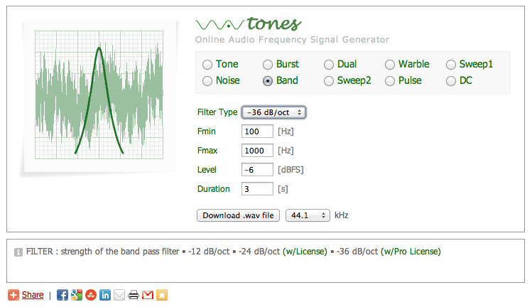
Playing the same sounds in f.ex. Sound Studio I can play them on continuous repeat, which Music doesn’t seem to do.
White noise generator by Pigeon
(Also see above chapter) myNoise: Have a look at https://mynoise.net/NoiseMachines/whiteNoiseGenerator.php. My speakers won’t really follow, but it’s nice to try this! Guess whether I liked this text, on the «donate» page:
«If the Internet were a busy town, myNoise would be its quiet public park. People come here to sit and relax. Unlike a city park though, there is no public funding : this friendly neighborhood website is entirely supported by people like you!» (Stéphane Pigeon)
Math /DSP
baudline
Update: This app could not run on macOS 12 (Monterey), so I have removed it 059:[macOS Monterey (12.x.y)].
by SigBlips DSP Engineering. From http://www.baudline.com/ I quote:
«Baudline is a time-frequency browser designed for scientific visualization of the spectral domain. Signal analysis is performed by Fourier, correlation, and raster transforms that create colorful spectrograms with vibrant detail. Conduct test and measurement experiments with the built in function generator, or play back audio files with a multitude of effects and filters. The baudline signal analyzer combines fast digital signal processing, versatile high speed displays, and continuous capture tools for hunting down and studying elusive signal characteristics.«
Also for MacOS. I found this in [16].
Update 19Apr2022. Installed baudline as the next to newest version = 1.08. According to baudline download then on macOS it requires X11 XQuartz-2.7.9 from 2016-05-05. When I started XQuartz I had (on my macOS Mojave 10.14.6) then it was XQuartz 2.76 from 2014, and I was asked whether I wanted to update to install 2.8.1 from 2021-04-26 – which I then nayed, and installed 2.7.9 instead. It’s a long time since I saw such an old looking tool. But I assume the math is still just perfect.
MATLAB
MATLAB (by MathWorks) isn’t too expensive used at home. It can be used with a plethora of toolboxes, see https://se.mathworks.com/store/link/products/standard/ML.
Scratchpad
Newest at the bottom.
Making it «BRRR»
Standard disclaimer, as always!
Finally (after a lot of searching, trying to make Google realise that I was after all kind of vibrators..), I found some rather good detail on vibration actuators. I actually came upon it by thanks to some very interesting boards from MikroElktronika. I have copy/pasted from most of this their pages .
Containing actuators from from JINLONG MACHINERY & ELECTRONICS CO., LTD:
- VIBRO MOTOR CLICK (product 2826) with Eccentric Rotating Mass (ERM) motor, labeled as C1026B002F (PicoVibe on the circuit diagram, 3.3V)
- VIBRO MOTOR 2 CLICK (product 3713) which contains a Eccentric Rotating Mass (ERM) motor, labeled as Z4FC1B1301781 (3.3V)
- VIBRO MOTOR 3 CLICK (product 4356). This board features the G0832022D, a coin-sized linear resonant actuator (LRA, longer life time than motors) that generates vibration/haptic feedback in the Z plane, perpendicular to the motor’s surface from Jinlong Machinery & Electronics, Inc. Driven by a flexible Haptic/Vibra driver the DRV2605 (I2C) (3.3V OR 5V)
- VIBRO MOTOR 4 CLICK (product 4825). This board features the G1040003D, a coin-sized linear resonant actuator (LRA, longer life time than motors) that generates vibration/haptic feedback from Jinlong Machinery & Electronics, Inc. Driven by a flexible Haptic/Vibra driver, the DRV2605 (I2C) (3.3V or 5V)
Then there is a very good overview here:
Vibration Motor Comparison Guide – by Precision Microdrives.
- Eccentric Rotating Mass (ERM)
- Iron core
- Coreless
- Brushless
- Piezo
- Solenoid
- Linear Resonant Actuators (LRA) (longer life)
However, I have been thinking of using point 2 below, all sold by Adafruit (point 2 also at sparkfun):
- Small Push-Pull Solenoid – 12VDC (product 412) current 300 mA. The solenoid is TAU0730TM-14, produced by CHAOCHENG TECHNOLOGY, data sheet at https://cdn-shop.adafruit.com/product-files/412/C514-B_Specification.pdf. I used this in My aquarium holiday automatic fish feeder (for granules)
- Mini Push-Pull Solenoid – 5V (product 2776) current 1.1 A (anonymous) – but I also find it at sparkfun at https://www.sparkfun.com/products/11015 where it’s identified as ZH0-0420S-05A4.5 SHENZEN ZONHEN ELECTRIC APPLIANCES Co., Ltd. (0.3 mill cycles), data sheet here (throw 4.5 mm, not 6 mm)
- Large push-pull solenoid (product 413)- 12V current 1A (anonymous)
I also find solenoids on several of the electronic distributor’s I use (Mouser led me to sparkfun, Elfa Distrelec led me to TDS, but Digi-Key probably has the largest selection).
Trigger other to do «BRRR»ing
The person I’m making this for has a BE1370 alarm clock from Bellman & Symphon (here, with Standard disclaimer, as always). Maybe I should use its external trigger input and have it make all the noise and also handle acknowledge of it? There are several sounds in it, including a pillow alarm unit with an eccentric motor inside. Or perhaps have something like this as an option?
 I mailed Bellman & Symphon in Sweden for the trigger spec. They sent me this figure (and okayed its use here).
There is a stereo 3.5 mm trigger input. Tip («spets»), ring and sleeve («hylsa») (see here) need to be connected as seen in the figure. Within 20 ms is should detect the trigger, which must be off for 30 seconds for any next trigging. Deliver 2-30 VDC or 3-24 VAC (5-150 Hz, I assume sine) as seen between ring and sleeve. The impedance is given by B&S to be around 10 kOhm resistive to ground. (However, I measured the unit I have access to, and it had around 26 kOhm internal resistance. By the way, it also triggered when the audio plug was plugged and when it was removed. I kind of like it!) Using a MOSFET transistor instead of relays, I don’t know, since I assume that they would need some driving voltage. But alternatively a relay may be connected at two places. A rather wide and good spec for an external input, if you ask me.
The only thing I miss is some means to detect that the cable indeed is connected. They could have done this by supplying f.ex. 5V through a 10k at the ring (a current output of 0.5 mA), and asked the inputter to hold the line down when not alarming. Both units could then use that voltage (low) to check that the cable is connected. The alarm clock would in this case see a disconnected cable as an alarm, or even a fault indicating that the inputter was dead (not able to surge that current). However, if the 3.5 mm female connector had a switch it would be able to differentiate. But, as in all designs, matters need to be compared. The input-only spec then probably couldn’t be as versatile as the one they have now.
LSTM
14Jan2022: With the new xcore.ai, maybe using Long short-term memory (LSTM) to distinguish sound is a viable path (thanks, student!). This may be mentioned in the XMOS literature as well. Maybe I could even make a hand-coded algorithm based on this to treat the peaks of sequences of spectra (after FFTs) to detect any type of alarm? I could ask the user to have my unit «record» the alarm sound and then just fix some parameters to have it included as the set of sounds to relate to (or not relate to). I read in Wikipedia that «a recurrent neural network (RNN) is a class of artificial neural networks where connections between nodes form a directed or undirected graph along a temporal sequence» (Wikipedia RNN here). Maybe «temporal» is the opposite to «frequency domain» – or maybe temporal for my case would imply a sequence of some sort only? Then, about LSTM, from Wikipedia (here):
Long short-term memory (LSTM) is an artificial recurrent neural network (RNN) architecture[1] used in the field of deep learning. Unlike standard feedforward neural networks, LSTM has feedback connections. It can process not only single data points (such as images), but also entire sequences of data (such as speech or video). For example, LSTM is applicable to tasks such as unsegmented, connected handwriting recognition,[2] speech recognition[3][4] and anomaly detection in network traffic or IDSs (intrusion detection systems). (14Jan2022)
Also see Introduction to LSTM Units in RNN by Gaurav Singhal [17]. From the student report where I found all this I quote, for back-ref to myself: «The LSTM model has been implemented in 64-bit version of Python 3.9.8. Pandas and Numpy libraries have been used to treat and manipulate the data set, while TensorFlow, Keras and Scikit-learn have been used to make the model. The Matplotlib library has been used to graph, visualize and show data and results.»
Shorting an output pin
9Apr2022. I think I may have broken the 1I output pin (X0D24 pin 88 on the chip). I now am making a new connecting board with serial resistors R3-R6. See Fig.1. I now see that twisting the shielded cable just a little was the problem. It was almost enough to change my mind or just look at it, and the short came and went. I hadn’t used shrink tube around the end of the shielded cable, so an individual wire strand from the shielding made these volatile shorts. Stay tuned.

Fig.20 Not protected shield caused a short to GND through one of its blank strands. Red arrow. Fixed: green arrow. And port XS1_PORT_1I returned from its rather volatile death!
10Apr2022. On page 24 an 25 of [3] I read that for Electrical Characteristics, Absolute Maximum Ratings that
I(XxDxx) GPIO current is -30 to 30 mA.
The DC Characteristics, VDDIO=3V3 (page 25) says that at allowed outputs low (0.4V) and high (2.2V) then these are
Pins X1D40, X1D41, X1D42, X1D43, X1D26, and X1D27 are nominal 8 mA drivers, the remainder of the general-purposeI/Os are 4 mA. Measured with 4 mA drivers sourcing 4 mA, 8 mA drivers sourcing 8 mA.
Then I read at the xCORE Exchange at (xCORE-200 Voltage/Current Protection from 2016 (before the XUF216-512-TQ128 processor?) that the xCore pins are not short circuit safe. This is contrary my experience, I certainly have had short-lived shorts by not being too careful with the scope probes, at least.
But then the quoted [3] doesn’t seem to tell that XUF216-512-TQ128 pins are short circuit safe either. After all, by exercising of the pin wasn’t with 100% on, I did have some duty in my cycling.
If my output should deliver 4 mA at 2.2V, then the resistance of the upper MOSFET transistor i (3.3-2.2 V / 4 mA = 1.1/4 mA = 0.275 k. If it’s linear then a full short would P (mW) = R*I*I = 0.275 V * 4 mA * 4 mA = 4.4 mW. Provided that the MOSFET behaves like these back-of-the-envelope assumptions, this short should not have hurt the chip. I assume that the output port transistors’ footprint is large enough to be able to absorb and drain the generated heat away, even if the dimensions are small. Guessing again, we are probably talking about some 300 * 300 µm or some 1/11 mm2. I may have missed by a factor of 10 too wide (30 µm square → 1/111 mm2) for all I know. But then, that’s inside back-of-the-envelope range.
So be it. When I got the new board soldered, with 1k serial resistors just for the case (not I2C SDA, SCL), including shrink tubes to insulate the strands in the cable shields, my output port pin raised to any level I would want it to. That means, all is fine! My two boards are both fine. I did test with my spare board, but since the wind blew in another direction then, it also exercised this pin on ground level. Even if I measured the pin before I powered it up. Or may I didn’t. It depends on that wind. However, also that board survived!
By the way, if that output had been broken, I had found a last resort solution, after some tumbling around. One of the on-board LED outputs could have a wire connected to the correct pin on J5. The connection from pin 88 could easily be removed with a scalpel, to get rid of competition, so to say. Even from a dead pin. Provided the physics of the chip allows for a single point of failure like this.
Uninterruptible Power Supply (UPS)
I would need an UPS for this. The problem is that the batteries should withstand being permanently getting idle charged. We used to use lead batteries for this at work (for fire panels), and I still have one for that system in this house.
Presumable one UPS that delivers both 5V and 12V. I found this: 7800mAh Power Bank UPS Battery Backup with 12VDC Output and 5V USB Port. I have queried them about MTBF but have got no answer.
Then Wired has an overview here: The 12 Best Portable Chargers for All of Your Devices by Simon Hill and Scott Gilberson in Oct2022. They have an interesting term called pass-through:
«Pass-through: If you want to charge your power bank and use it to charge another device simultaneously, it will need pass-through support. The Nimble, GoalZero, Elecjet, Biolite, Mophie, and Zendure portable chargers listed support pass-through charging. Anker discontinued support for pass-through because it found that differences between the output of the wall charger and the input of the device charging can cause the power bank to cycle on and off rapidly and shorten its lifespan. We would advise caution when using pass-through, as it can also cause portable chargers to heat up.«
I don’t know whether this effectively is the same as having the functionality of an UPS, but I’ll ask Nimble.
14.4.1 on a reserved machine!
After XMOS obsoleted xTIMEcomposer I did install it on a reserved machine. See My XMOS XTC Tools notepad. It’s a Mac mini from 2010 and runs macOS (OS X) Sierra 10.12.6. Update 13Dec2022: xTIMEcomposer Big Sur macOS 11.
Alternatives
iOS «Sound Recognition»
(Norwegian: Tilgjengelighet → Lydgjenkjenning). According to Wikipedia iOS 14 then «A new Accessibility feature, called Sound Recognition, allows iPhones to listen for predefined sounds and issue an alert whenever the specific audio is detected. This way an iPhone can detect fire, various sirens, animals, multiple household noises, and a baby that’s crying or someone that’s shouting». Observe it’s not an app as such, but an «accessibility feature» or just «accessibility setting» (No: «Tilgjengelighet»). (Aside: It also seems to work on the iPhone SE (1st generation, 2016), which does not have any neural engine as such – but it does have and A9 with a dual-core 64 bits ARM, plus a PowerVR 6-core 32 bits(?) GPU. This phone even runs iOS 15.)
As it says on the iPhone’s Accessibility Sound Recognition switch:
Your iPhone will continuously listen for certain sounds, and using on-device intelligence, will notify you when sounds may be recognized.
Sound Recognition should not be relied upon in circumstances where you may be harmed or injured, in high-risk or emergency situations, or for navigation.
Update 20Feb2023. I discovered that on iOS 16 this tool has got customisation added: custom alarm. I now can create and record my own local sounds! (Norwegian: Tilgjengelighet → Lydgjenkjenning). I could do Custom alarm or Custom Appliance or Doorbell (Norwegian: Tilpasset alarm or Tilpasset apparat eller ringeklokke). When I tested it it wanted to record the sound five times. When I played the doorbell sound I have (and which my recording does a one time recording only), I wasn’t able to get it to accept my sound. At least not five times. I tried over and over until it, for each of the five sounds, it was accepted. But I wasn’t able to get five accepted. I played the bell some 10-20 times but no. I had to give up. So I can’t tell how successful this is. (TODO: retest this!)
Infineon smart alarm system
I guess that when I started this blog (02Apr2021, with a board that has Infineon mics) Infineon was already working on their battery powered listening-for-audio unit. See Re-Inventing Home Security: Infineon’s New AI/ML-based Smart Alarm System (By by Amelia Dalton in Electronic Engine EE Journal (EEJournal) 19Aug2022) («industry-first acoustic event detection and alarm system» in the intro), plus at Infineon’s own page Smart alarm system. They use an Arm based PSoC processor – a PSoC 6 (CY8C6xxxx PSoC6).
Going for the machine learning stuff might be my mark II, should I want to port this to my XMOS «Voice reference design evaluation kit» XK-VOICE-L71 (containing an xcore.ai of type XU316-1024-QF60A-C24) – or other.
But then, when I tested the Apple iOS “Sound Recognition” app (above) it didn’t really shine.
Forums
XMOS ticket submissions
Doing this, even if xTIMEcomposer 14.4.1 is not updated any more. But I assume that some of the code is reused in the new toolsets.
- «linker or xmap error: blips in sound output switched on and off by adding an unused xassert(false)«. By me, 11Mar2022. XMOS ticket number #183751. In it are also referenced point 6 in the xCore Exchange forum list, below. If you are here some days after 11Mar2022, the full attachment to XMOS may be downloaded from https://www.teigfam.net/div/teig_2022_03_11.zip (22.7 MB)
xCore Exchange forum
Newest at the bottom:
- Microphone array AN00219 no sound – mspit, 22Oct2019
- Filling out unused cores with while(1) – me, 28sep2021
- mic_array_get_next_time_domain_frame in a select? – me, 19Nov2021. Relates to Implementation D
- mic_array board and adc out time usage – me, 14dec2021. Relates to the same as the point above. Observe error in title and most of the place: ADC should be DAC of course!
- Power spectral density calculation coming negative – shaileshwankhede (2Dec2016)
- Glitches in UAC2 while doing playback – by SonnyDK. 6Mar2022. Also see point 1 in the XMOS ticket submissions, above
- Combining bit reverse and time reverse of a sequence in asm – me, 21Jul2022
- xrun: Cannot load image, XCore 0 is not enabled – me, 05Dec2022 for a broken XK-USB-MIC-UF216 (XCORE MICROPHONE ARRAY EVALUATION BOARD)
- Status of XCORE-200 EVALUATION KIT (XK-EVK-XE216) – me, 06Dec2022. I will move to this board and park the single mic array board I have
Stack Exchange
Electrical Engineering
- I have an XMOS 7-mic board using the CS43L21 for ADC output. I get it working at 48 kHz, but not at 8 kHz, following the example of XMOS AN00219 – me, 18Dec2021. Observe error in title and most of the place: ADC should be DAC of course!
- May I write to a DAC chip slower than data is «sampled» at? – me, 28dec2021
Signal Processing
- Impulse response of IIR low-pass filter – me, 21Apr2022. Answered there!
- Low-pass vs. windowing function in front of FFT – me, 21Apr2022
- Sampling, filters, windowing, FFT. From theory to help on this coding list– me, 12May2022
- Taking every third value or the mean of three – me, 10Jun2022
- Equalizing my speaker’s output via mic input, forming slow automatic gain control over some frequency range – me, 13Jun2022
- Detecting a known alarm signal in an audio stream – me, 20Jul2022. Do cross-correlation as in [29] or filter the analog signal for «bah» then «buh» etc.
Stack overflow
- Memory FRAM MB85RC256V data sheet interpretation – me, 30Oct2022
[[TODO]]
- I already have done formal verification of the knock-come pattern (above: «Implementation D («knock-come») in Promela with the Spin model checker. Will I ever have time to verify this in (1) CSP using FDR4 or (2) Event-B (B-method) using the Rodin tool?
References
Wiki-refs: Audacity. Autocorrelation. Baudline. Communicating sequential processes (CSP). Complex conjugate. Complex conjugate root theorem. Decibel. Delta-sigma modulation. Digital biquad filter. Digital filter. Fast Fourier Transform (FFT) [19]. FIR filter (Finite impulse response). I2C. libfixmath. Long short-term memory (LSTM). Microelectromechanical systems (MEMS). Nyquist–Shannon sampling theorem. PDM. Producer–consumer problem. Recurrent neural network (RNN). Smoke detector. Spectral density (Energy spectral density (ESD) and power spectral density (PSD)). Q (number format) (also see [8], q_format, Q-format)
|