Contents
- 1 Fold handling with Collapse-O-Matic plugin
- 2 Intro
- 3 Processor boards
- 4 AudioMUX
- 5 dB (decibel)
- 6 Other measurements
- 7 The menu
- 8 Using more inputs
- 9 The softblinking LED PWM
- 10 The code
- 11 The code (download)
- 12 Second thoughts
- 13 User forums
- 14 References
Started 29May2020. Updated 08Feb2024 (Online Tone Generator another reference).
This note is in group Technology (plus My XMOS pages). Since our daily (mostly spoken word) radio listening seemed a little too «bassy» for me, and I had a nice processor board really lost behind, I thought that now was the time to have some fun and get rid of some bass. And maybe add some treble. That’s what I thought was going to be this project. (I have another audio blog note at My subwoofer notes.) Update 19Nov2020: I moved some chapters from this note into a new note: My button presses vs bounce vs EMI notes.
For the TIOBE index 016:[10]: «XC programming».
Fold handling with Collapse-O-Matic plugin
I am using Collape-O-Matic (here) on many pages.
| Collapse All |
Typical fold
Intro

Fig.1 Three buttons and a display, plus a new box from the basement shop
The ARGON DAB+ tuner delivers signal over a 3.5 mm analogue line output jack’ed cable to a small ARGON speaker that has more bass end less treble than I like, when they are talking about something interesting on the radio ([7], [8]). Bass boost is my only choice. The speaker also has Bluetooth, but that doesn’t help with my problem. Besides, the tuner has no Bluetooth output. My solution is definitively cabled. And since I haven’t found any way to control the bass and treble bands out of the boxes, I searched for, and found, a small board called AudioMUX with an I2C chip from ST called TDA7468D ([5], [6]). At first I thought I could make some digital filters, but why not. Here gain, bass and treble levels are handled with analogue circuits, controlled via I2C from a processor. The bass crossover frequency cannot be changed, but then, my speaker isn’t a soobwoofer. And then, I had thought I could sell my two obsoleted XMOS boards, but since I had not come around to doing that, why not use one of the xCORE-XA Code Module boards for this? ([1], [2], [3], [4]). So far, the XC code is going well (141), and I have 8 logical cores to do it on (see 7/8 cores?). But the ARM® Cortex®-M3 that also is on board is causing me trouble. However, since I ended up with a startKIT board instead, let’s just preempt much of this note with the below chapter:
Processor boards
I had two different types of obsoleted XMOS boards. Two of the xCORE-XA Code Module boards. They are both now for sale! Just mail me and we could agree on a price. And I had two unused startKITs. I ended up with one of those. Since the startKIT also has reached end-of-life (here) I would have chosen an xCORE-200 eXplorerKIT should I have started anew.
I keep all the text about the xCORE-XA for the one person out there who has one and know how to flash them. Or the hopefully many who have the time and want to read more than they think they need to read. You?
As said, I gave up on trying to flash the xCORE-XA board. The solution with the USB power bank battery (No success yet, below) was ok for three months. But I figured that I all in all had four startKITs. Even if they have been obsoleted a while now, they are incredibly nice to work with. One is used in my aquarium controller box by the fishes, one in the bench version of it, one now in this project, and I still have one to spare! I will come back with the updated code and diagram.
All this said, it would still have been nice if someone could find out how to flash the xCORE-XA board. See points 1 and 3 in XCore Exchange forum (below).
Using the startKIT with flashed code
Summary

Fig.15 – My final (and flashable) solution using an XMOS startKIT (press for more pixels) (Label before all inputs could be used)
I guess the picture speaks for itself. I had to make a new, nicer no-hole right side. I also made the softblinking LED float in thin air with a diffuser in front. I only soldered connectors where needed. In the xTIMEcomposer development tool I only changed from one board to another, and remapped the I/O and the code was running. Well, not really. I decided to keep the old project and make a new one for the startKIT. When all the sources had been imported and remapping done, everything worked from first trial.
EMI as sitting on the top of a fridge
This chapter has been moved into a separate note: 214:[EMI as sitting on the top of a fridge]
startKIT’s external connections
fig17_208_external_connections_startkit_oyvind_teigFig.16 – External connections with startKIT and AudioMUX, Adafruit #931 display and three buttons (PDF, JPG)
The startKIT code
Using a xCORE-XA Code Module and not flashing the code
First and final point: FLASHing the code
No success yet
At the moment (20Jun2020) I have not succeeded in flashing the code, neither with the XMOS XFLASH tool nor the xTIMEcomposer 14.4.1 (or 14.3.3) development system. This is so sad that I made the picture below rather colourless (so that I have something to celebrate when it’s solved). Especially, since the nice XC code now does all that it’s supposed to. As always it’s been a thrill to work with this tool.

Fig. 6 – The xCore-XA Core Module runs with code in RAM by the help of a power bank (190 mA current drawn)
Therefore xCore-XA board runs with code in RAM by the help of a power bank. I download the code for debug in the xTIMEcomposer and just unplug the XTAG USB connector and walk it to the destination and from then on continuously charge the power bank from the mains. (I haven’t checked if this would have worked if I had done any printf’s. I don’t.) Should the power now fail, if the USB 5V cable slips out, or the mains falls out and the battery is discharged, then the box will not have any start-up code.
In the following chapters there is a thorough discussion which probably shows why I have failed. Or isn’t it me? Also, follow the User forum threads (below).
But here is the present (21Jun2020) scenario on macOS 10.13.6 High Sierra and xTIMEcomposer 14.4.1:
myMachine:~ teig$ /Applications/XMOS_xTIMEcomposer_Community_14.4.1/SetEnv.command
bash-3.2$ xflash /Users/teig/workspace/_AudioMux_controller/bin/_AudioMux_controller.xe
Error: F03122 No Arm Binary supplied, please use option --arm-binary
bash-3.2$ xflash /Users/teig/workspace/_AudioMux_controller/bin/_AudioMux_controller.xe --arm-binary /Users/teig/workspace/_AudioMux_controller/bin/_AudioMux_controller
Error: F03139 xCORE image is too big for the ARM flash partition
bash-3.2$
The XMOS processor
Aside: The more I look at it, the more fantastic I think this architecture is. A union of the most ported processor architecture in the world with the best processor architecture (even with a scheduler) and programming language (that would have deserved to be in much wider use, all in my opinion, of course (disclaimer)) is just great. Still, I do understand, both why XMOS developed it and why they dropped it. I assume that they wanted to concentrate on their own architecture (which, years on, should have been much more used in embedded and safety critical than mostly audio), and if people wanted an ARM on the same board then throwing one in would probably not add substantial cost anyhow. Even if that would be without the xCORE-ARM bridge. Therefore, here’s the sad conclusion:
End of life reached
Just to repeat it: xCORE-XA Core Module EOL [1]. This would go for the xCORE-XA Code Module board and its processor. Plus for the xTIMEcomposer tool some time after May2020. Both for the XC and C code. However, it was just too bad to have to throw my two boards away, without ever having used them. After all they cost 149$ each in Feb2015. Only now did I find anything to use them for. (To the rescue would be was the fact that I could easily move the XC code to any of my other boards like the obsoleted startKITs or the xCORE-200 eXplorer boards. But I would have to make a new box, (wrong: the startKIT is smaller than the xCORE-XA board) which is out of the question since the DAB+ tuner fits in position on top of my present box.)
XS1-XA8A-10-FB265
The processor on this board is XMOS
XS1-XA8A-10-FB265   // Processor according to [2]
XS1-XAnA-1024-FB265 // Package according to file "XCORE-XA-MODULE.xn" in xTIMEcomposer
XS1-L8A-64          // Type --"--
But according to the single post found about it on XCore Exchange (point 2 below) the data sheet was under NDA. However, when I searched my own notes I found a chapter in note 098 (here) where I did find an XMOS reference to it [13].
The ARM core
ARM® Cortex®-M3 is a 32 bits processor. XMOS is the manufacturer, even if [13] has reference to Silicon Labs. I found this by trying out Silicon Labs’ core EFM32GG230F1024. More below.

Fig.2 – Processor board and AudioMUX. Without the labels I later made
Trouble with the ARM® Cortex®-M3 core
I have no need for the ARM core
I have no need for that core. If I had, I would have used one of my Arduino Zero ARM, the ATSAMD21 Cortex-M0+ core boards that also are somewhat lost behind. They are nice, but I would rather use my time for a full multi-core processor with a beautiful language (than pure C, C++ or Python). For me the goal mostly is the road. (And yes, I do have problems with lots of this XMOS and XC stuff. Some times the road seems rather long. But then I do something else and come back on the road again. I almost just left that road. But then I decided to write up the start of this note instead, and take it from here.)
Expected behaviour not present
No Debug or Run of ARM code
My code, as compiled by the XCC compiler of the xTIMEcomposer (more about XC, start here) will «Debug» ok. I have then set XCORE_ARM_PROJECT = 1 in the makefile, I can include or exclude the dummy c file compiled for the ARM code (that should just blink the ARM user LED anyhow, code taken from an XMOS application report [9]) and the XC code will still Debug. But the ARM code will not follow suit. This is OK for me, since I’m not going to use it anyhow. This problem is discussed in point 1 in the XCore Exchange forum chapter (below).
Also XC code will «Run» (loaded and started with no further intervention from the debugger), but still not the C for the ARM core. But if I do this by right-clicking in the bin directory, on the [arm/le] file I get
xrun: Invalid executable file passed
but if I right-click on the [xcore/le] file the xCORE part starts running nicely. I get the same result with the newest xTIMEcomposer 14.4.1 and the older 14.3.3, with or without the -std=c99 parameter (needed for local declaration of the index variable in the for loops, which I declared globally in main instead).
No xflash of any code
Also, if I try to «xflash» burn the executable file generated by xTIMEcomposer (14.4.1 or the older 14.3.3) I get:
bash-3.2$ xflash /Users/teig/workspace/_AudioMux_controller/bin/_AudioMux_controller.xe --arm-binary /Users/teig/workspace/_AudioMux_controller/bin/_AudioMux_controller
Error: F03139 xCORE image is too big for the ARM flash partition
→ This may be because the I don’t have the SEGGER GDB J-Link driver installed. Is it? What counts against this is that «Debug» and «Run» work for the XC code on the xCOREs. But then, the C code for the ARM core does not.. because it needs the SEGGER driver?
No SEGGER GDB driver
There is a lot about this in the xTIMEcomposer User Guide [10] (like page 239). And in [4] my board is depicted, and on the bottom side it’s even printed ON BOARD DEBUG www.segger.com J-Link OB. So this board has two hw debug chips: the XTAG chip plus the J-Link chip (an STM32). The latter’s JTAG header is available as open tabs, but the chip is also connected to the common USB chip (CY7C6563X) over a serial line (JLINK_DN / JLINK_DP), similar to how the XTAG chip is connected over two serial lines (XTAG_HUB_D_N / XTAG_HUB_D_P and (?) FSB_USB_D_N and FSB_USB_D_P). This makes both worlds available over the USB. (More about this below)
The driver for the XTAG comes with the xTIMEcomposer. But not the SEGGER driver. When installed this command should make sense [10] (page 242):
./JLinkGDBServer -if SWD
I would then need to have usr/local/bin/JLinkGDBServer installed. I have tried this, but failed [11]. Since I could not find any binary server download I got permission from SEGGER to download the J-Link GDB Server RTOS plug-in SDK which obviously is a dead end. I don’t need any API for the Eclipse. This would have been for the XMOS designers, since xTIMEcomposer runs under Eclipse.
I am stuck, I don’t know where to find the JLinkGDBServer.
ioreg
I remembered that I did have som closer contact with the USB when I this winter started working with the mySTorm IceCore FPGA (here). I then brought that knowledge over here and did the following:
bash-3.2$ ioreg -p IOUSB
+-o Root  <class IORegistryEntry, id 0x100000100, retain 15>
  +-o AppleUSBXHCI Root Hub Simulation@14000000  <class AppleUSBRootHubDevice, id 0x10000032a, registered, matched, active, busy 0 (17 ms), retain 13>
    +-o ... several, like Keyboard
    +-o USB2.0 Hub@14200000  <class AppleUSBDevice, id 0x1000074bd, registered, matched, active, busy 0 (6 ms), retain 13>
      +-o J-Link@14230000  <class AppleUSBDevice, id 0x1000074d9, registered, matched, active, busy 0 (16 ms), retain 11>
      +-o XMOS XTAG-PRO@14220000  <class AppleUSBDevice, id 0x100007507, registered, matched, active, busy 0 (36 ms), retain 17>
The J-Link certainly is available!
Do I need J-Link EDU?
Do I really need to buy a J-link box, like the J-Link EDU? I think [12] contains a description by GNU MCU Eclipse on how to install JLinkGDBServerfor macOS. There they say that «The J-Link binaries are available from the SEGGER site» and when pressing the url SEGGER redirects and does not take me to any binary files page, but to [11]. This may have changed from Jun2018. But SEGGER there writes that « J-Link Software and Documentation Pack. Can be downloaded and used free of charge by any owner of a SEGGER J-Link, J-Trace or Flasher model.» The J-Link model overview they show here. I did download the SW and I now have the JLink_MacOSX_V680a.pkg on my iMac. Installing it I now have /programs/SEGGER/JLink_V680a See next chapter.
In [12] they continue that:
The result of the install is a folder like
/Applications/SEGGER/JLink_V641b/(a different folder for each version) where all executables and libraries are stored; please note that, as for many macOS applications, no other driver files are installed in the system folders, but some symbolic links are created in the/usr/local/binfolder.Be sure to update the path in Eclipse preferences page to point to the latest SEGGER J-Link software.
USB
On macOS, the USB subsystem automatically identifies and allows access to USB devices, without the need to maintain a manual list similar to the one used byUDEVin GNU/Linux. No other drivers or system configurations are required.
But the XMOS xflash does not seem to like my C binary for the ARM anyhow. And it requires me to use the --arm-binary (as shown above) when I also give it the xCORE executable. So I must be really sure that buying a J-Link EDU will solve my problem before I invest in one. I have a feeling it won’t. I guess XMOS would have written that down explicitly. Update: Maybe they did. In [2] I discovered this:
For debugging, an on board XTAG device is available for debugging the xCOREs and a JLINK-OB device is available for debugging the ARM core.
But then again, the XTAG device and the J-Link device probably are those chips that already are soldered on board my board, mentioned above. Provided on board points to both units. When one don’t know things by forehand it’s sometimes almost impossible to find out what’s meant. Wasn’t it Bertrand Russel who showed that all systems sooner or later must refer back to themselves?
Running SEGGER’s sw
JLinkGDBServer.app
Since I now have /programs/SEGGER/JLink_V680a I started the JLinkGDBServer.app. Here is some of what I found:

A new firmware version is available for the connected emulator- Do you want to update to the latest firmware version? NOTE: Updating to the latest firmware version is strongly recommended. New features / improvements may not be available without a firmware update
(See above figure) This is great. The processor is seen! For the time being I pressed No.

The connected J-Link (S/N 660003200) has been designed to work with devices made by XMOS only. Debugging the selected device EFM32GG230F1024 is not supported by this J-Link. To program and debug the target device, please consider purchasing a full J-Link. More information: https://www.segger.com/link-debug-probes.html
(See above figure) According to the SEGGER J-Link V6.80a – Target device settings XMOS is not the manufacturer of any ARM. But I did find a reference in [13] to Silicon Labs. And they do exist in the SEGGER manufacturer list. The core is has 128 KB internal single-cycle SRAM for code and data storage — 1024 KB SPI FLASH. The first almost matching I can find in SEGGER’s list is one with 1032 KB FLASH and 18 KB RAM. It’s: Silicon Labs EFM32GG230F1024 Cortex-M3. But when I set it, I got the above infobox.
In other words, it does not exist in JLinkDevices.xml. And not in /programs/SEGGER/JLink_V680a/Devices/*.
I did respond Yes to updating the emulator firmware (on «unspecified» target device) (lots of things happened, but the app quit and I don’t know where the log went).
I then double-clicked on the JLinkGDBServer reference. I got this:
OM11-kontor-2016:~ teig$ /Applications/SEGGER/JLink_V680a/JLinkGDBServerCLExe ; exit;
SEGGER J-Link GDB Server V6.80a Command Line Version

JLinkARM.dll V6.80a (DLL compiled May 29 2020 16:28:29)

-----GDB Server start settings-----
GDBInit file:                  none
GDB Server Listening port:     2331
SWO raw output listening port: 2332
Terminal I/O port:             2333
Accept remote connection:      yes
Generate logfile:              off
Verify download:               off
Init regs on start:            off
Silent mode:                   off
Single run mode:               off
Target connection timeout:     0 ms
------J-Link related settings------
J-Link Host interface:         USB
J-Link script:                 none
J-Link settings file:          none
------Target related settings------
Target device:                 Unspecified
Target interface:              JTAG
Target interface speed:        4000kHz
Target endian:                 little

Connecting to J-Link...
J-Link is connected.
Failed to set device (Unspecified). Unknown device selected?ERROR : Failed to set device.

Firmware: J-Link OB-STM32F103 V1 compiled Apr  8 2020 10:10:28
Hardware: V1.00
S/N: 660003200
Checking target voltage...
Target voltage: 3.30 V
Listening on TCP/IP port 2331
Connecting to target...
ERROR: No CPU core or target device has been selected. Please make sure at least the core J-Link shall connect to, is selected.
ERROR: Could not connect to target.
Target connection failed. GDBServer will be closed...Restoring target state and closing J-Link connection...
Shutting down...
Could not connect to target.
Please check power, connection and settings.logout
Saving session...
...copying shared history...
...saving history...truncating history files...
...completed.
Deleting expired sessions...1 completed.
Here is the error message that comes, after which it exits:

The selected device «UNSPECIFIED» is unknown to this version of the J-Link software. Please make sure that at least the core J-Link shall connect to, is selected. Proper device selection is required to use the J-Link internal flash loaders for flash download or unlimited flash breakpoints. For some devices which require a special handling, selection of the correct device is important.
JLinkConfig.app
I ran this after I had run JLinkGDBServer.app and updated from it. All of this makes sense. I gave it the nickname XMOS. But then, this does not relate to any ARM core.
SEGGER J-Link Configuration V6.80

Product = J-Link OB-STM32F103 V1 compiled V1.00
Nickname = XMOS
SN = 660003200
USB = SN 660003200
HostFW = 2020 Apr 8 10:10
EmuFW = 2020 Apr 8 10:10

Updating firmware of probe/ programmer 1 of 1 via USB (SN: 660003200)...Not updated, probe/ programmer firmware is already up to date.
I added my second xCORE-XA board and restarted JLinkConfig, and got this status. I selected to keep the old firmware, just for keeps. I see that the SN is kept for any USB connection.
Product = J-Link OB-STM32F103 V1 compiled V1.00
Nickname = XMOS-2
SN = 660003229
USB = SN 660003229
HostFW = 2020 Apr 8 10:10
EmuFW = 2014 Feb 5 13:48 (Old)
I also see that the ARM Debug Status LED on the xCORE-XA is blinking before the board has been seen by some SW. If I try to connect both USB (debug and power) to power only, the debug USB blinks. Only when the debug USB is connected to the machine does it stop blinking and is steady on. Some SW sees it. I wonder which?
xCORE-XA Core Module
xCORE-XA Core Module and 5V

Fig.5 – xCORE-XA board’s USB circuitry (XMOS, [3]) (press for more pixels)
Aside: XMOS does not have any serial Schottky on the xCORE-200 eXplorerKIT board, but the board also has this varistor(?) 330R @ 1700 mA in the plus wire only – exactly like on the startKIT board.
xCORE-XA’s external connections
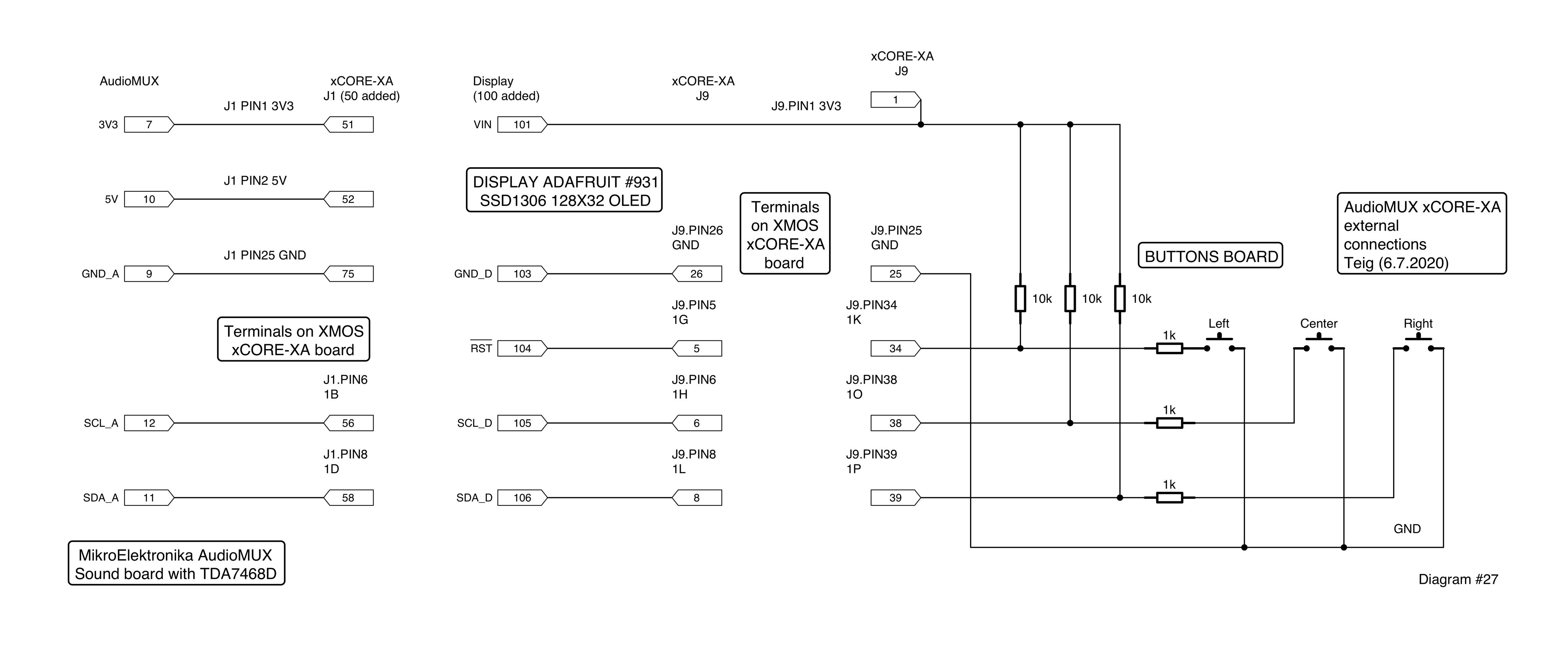
Add this diagram and the (nice to have) modification of the AudioMUX in Fig.4 (above) and you have it. I used two I2C buses (as also seen in the code) for the simple reason that I wanted the connectors to the display and the AudioMUX each to be cabled and plugged separately. I draw with iCircuit. But, alas, it does not let me group connectors, so I had to add 50 and 100 to make the numbering non-overlapping.
(However, have a look at the later startKIT’s external connections (above); that’s the final diagram, used after I discovered the EMI noise, causing me to migrate this stuff into a new note My button presses vs bounce vs EMI notes.)
fig14_208_external_connections_oyvind_teig_Fig.14 – External connections of AudioMUX, Adafruit #931 display and three buttons (PDF, JPG)
AudioMUX
TDA7468 I2C chip
I have annotated page 6 of the data sheet [6]. Press the picture for higher resolution. The PDF of the page is here. The reason for doing this is for understanding. The figure should talk for itself. Observe that I have added the I2C control arrows of Volume2 and added the Mute switches at the far output. (An aside: I could think that this diagram is nice, but have a look at the diagram in a magazine from 1925, at note 203 here.)

Fig.3 – TWO BANDS DIGITALLY CONTROLLED AUDIO PROCESSOR WITH BASS ALC SURROUND © 2010 STMicroelectronics. www.st.com April 2010 (Rev. 4). Page 6. Annotated by Øyvind Teig (2020) (PDF)
I am writing my own set of drivers, in XC. See Code below.
Frequency response
From [5] we read that:
«The EQ sections can adjust bass and treble frequencies in the range from -14dB to +14dB, in 2dB steps. The frequency response of these sections is determined by external RC elements. The Click board™ has these values optimally selected for the best performance. The low-frequency range is processed by a T type bandpass filter with its center frequency at around 32Hz, while the high-frequency range is processed by a high pass filter with the -3dB attenuation point at about 3kHz. A single register is used to control the entire EQ section (TREBLE & BASS register).»
As already mentioned, the bass crossover frequency cannot be modified. But this is indeed selected, one and for all, by the RC-components’ values. I found no need to modify the AudioMUX’s values. It would have required unsoldering of components, something which I bought the board to avoid. But the formulae is in the TDA7468 data sheet [6].
I2C address
I2C does not support 8-bit addressing, like the TDA7468 data sheet seems to indicate. It supports 7-bit or 10-bit addresses. STMicroelectronics has bluntly included BIT0, which is the R/W bit (1=read, 0=write), into the 8-bit «address» that they state to be 0x88. Since the TDA7468 only supports writing, then BIT0 is always 0. So the first byte to write to the bus would be 0x88, but the address part of it is 0x88>>1 = 0x44.
AudioMUX and +5V power selection
I needed to be able to test out the AudioMUX with the TDA7468D with higher voltage than the bare minimum 5V (according to the data sheet [6]). But I needed to select and unselect internal power from either source, the microBUS™ or EXT/VIN. Doing that by soldering several times on the 0 Ohm JP1 for VCC SEL I did not fancy. I have seen printed circuit board’s with destroyed tracks from excessive soldering. I needed «dynamic» VCC SEL. The AudioMUX has a designed-as solder-once solution, probably to keep the price down (and earnings up, which is fair) and thinking about typical usage, which I assume is not like mine.

Fig.4 – Some soldering and the MikroElektronika’s AudioMUX’s TDA7468D gets jumper-selectable power. Observe that it’s goodbye to Click board™ usage! Diagram from [5] (press for more pixels)
VCC SEL jumper: green position (see figure) from microBUS™, blue position from VIN (EXT) connector. I did this:
- Unsoldered the J2 resistor. MikroElektronika call it «jumper» but I’d say it’s not easy to jump with it. But they had nicely inserted it, which was nice, since this then gave me two free solder pads
- Wired between one pad to pin 13 (the one above SCL). See fig.4
- Wired between the other pad to pin 14
- Wired between pin 15 to the EXT pad on the vacant VCC SEL
- Wired between pin 16 and GND. This makes possible to not use the screwed terminals on VIN, but to use a three point connector EXT:EXT:GND at the end of a two-wired cable. In that case the jumper is not needed. I did not need it
I could have just soldered a 3-pin connector instead of VCC SEL JP1, but the board does not have any through holes for those pads. I therefore did not want to do this, as it could easily cause the thin track on the board to get ripped off. After all, this board is quite expensive.
At the end of the day it turned out that my problem with not getting any sound through was not low voltage to the TDA7468D. Even the 4.72V supplied by the xCORE-XA board turned out to be sufficient (see chapter «xCORE-XA Core Module and 5V» above). The problem was that «Surround gain» register R2 [BIT2..BIT0] have no meaning and [BIT5..BIT3] must be set correctly! Stay tuned.
AudioMUX needs protection

Fig.7 – The MikroElektronika AudioMUX board comes with no protection against inadvertent shorts. I made one from silicon (press for more pixels)
I saw that it was easy to miss the 3.5 mm connector holes and unintentionally have the metal in the jacks touch the board. A short might have been a good bye to it! So I made one from silicon, since it was easy to cut about right and it sits quite well all by itself. If MikroElektronika picked up this free tip then I suggest they make it from cardboard and at the same time print the IN1-4 and OUT texts there. I made some labels on the base:

Fig.8 – Labels also needed (press for more pixels) (With startKIT and all inputs possible)
dB (decibel)
See Wikipedia (below).
There is a factor of 10 for every 20 dB for the amplitude. +20 dB value is then ratio 10/1 (gain) and -20 dB is ratio 1/0 (attenuation).
- 0 dB is unchanged. For volume, bass and treble it means nothing is added or subtracted.
- -3 dB is about 1/1.4 ≈ 0.7
- -6 dB is about the 1/1.995 ≈ half
- -20 dB is 1/10 = 10%
- -40 dB is 1/100 = 1%
- + would be gain of the same values
To confuse or make clearer (choose any), then read the two blog notes by Niklas at LogiSon about decibel and subjective factors, see [17].
1 kHz sine attenuated in -1dB steps
I used the Online Tone Generator 219:[Online Tone Generator] and measured.

Fig.11 – 1kHz input attenuated by -1db steps. Siglent scope (obs hairy output and CH2 probe is 1/1 not 1/10) (press for more pixels)
The diminishing purple curve is recorded in scope roll mode with 1.0 sec/part. The lower inset shows the two 1 kHz curves. The upper inset shows how I decided to rather sacrifice two older 3.5 mm audio cables and measure directly than sacrificing, ie. measuring with possible unluck of a pathological short, on the AudioMUX board itself.
The BASS and TREBLE controls were at 0dB.
This shows that decibel, dB, in this context certainly is the amplitude, not the power.
Observe that with 400 mV peak to peak (p-p) the «voltage» as measured by a meter on this sine type waveform, is not even 200 mV. The RMS (Root mean square) voltage is 200 / √2 = 141 mV. This is what a multimeter on AC (Alternating current) will tell you. In other words, our AC audio signal of 400 mV p-p will heat up a resistor as much as a 141 mV DC (Direct current) voltage.
Two asides: When I made the sine scope measurement I saw that I needed to ground both scope probes. The -1dB step (the larger part of picture) has the attenuated cable not grounded, so it is somewhat hairy. I did not redo it, because it does show the point. I also all of a sudden also saw that the CH2 scaling says 10X but probe was set to 1X. I have been used to even more expensive probes and scopes at work over the years, where the scope’s setting for the probe automatically changed when the probe’s switch was changed. It took me now. I didn’t see the discrepancy before after I made Fig.11. So the 50mV/part on CH1 certainly does correspond to 500mV/part on CH2, so the picture is ok’ish. Again, I’ll keep it. The point is probably shown clearer. But Fig.12 (below) has the CH2 probe set correctly.
Other measurements
Signal processing micro course
In signal processing sine waves, square waves and delta pulses are particularly interesting signals. A pure sine is represented by itself. Finito. Then come signals where there is something abrupt, or discontinuous. Like when you break a flower’s stem and it tilts from there, provided it’s not two pieces. A square pulse has four «corners» per period, so to represent it we would need several sines added, in a particular system: represented by overtones or harmonics. A delta pulse is what you make when you clap hard once in a big church and listen to the echo and how it dies. Then you’d have the church room’s transfer function. I have read that Bach did this when he got an order for a musical piece, meant to be played in a certain church. The nature of the echo describes the room. As every bat would know. To analyse which harmonic components a signal consist of, Fourier analysis is used. On a computer it’s the Fast Fourier Transform (FFT) that is often used to get the individual components. (I remember seeing a mechanical machine from the 18th century at Science Museum in London which did this with ball-and-disk and drew the result with a pen on a paper. I think it’s described as James Thomson’s Harmonic Analyser in 1886 in the Ball-and-disk integrator Wikipedia article (below)).
I concentrate on square waves, because it’s ueasy and fun. Also see Wiki-refs Fourier analysis, FFT, Sine, Delta function and Square wave (below).
Micro course extra value. To find the curve «gain as a function of frequency» I could have ordered a scan with a sinus (from 20 Hz to 20 kHz) and seen how it came through the TDA7468 with the scope in Roll mode. Something like in the Fig.11 large curve. This would be the frequency domain. But that curve is in a way given in the data sheet, so I didn’t actually do this. However, I could also have given the input a delta pulse (a micro second pulse?) and measured what came out and then used the oscilloscope’s FFT function to present that signal, also in the frequency domain. The curve I would have seen then would in theory be the same as the gain/frequency curve. We used this technique at work to measure distance to oil surfaces in oil tanks in large oil tankers. We used a scan of GHz radio signals, and we then analysed the echo by an FFT. That gave us the distance domain, and we could search for a top in the curve. I remember I wrote the FFT from a Fortran program in the textbook to Pascal and then to assembler. This is so fun, I do recommend playing around with it.
1kHz square with treble and bass changed
Square wave from online

Fig.12 – Square wave signal and FFT (press for more pixels)
Fig.12 shows a 1 kHz square wave and what happens with the output when the BASS and TREBLE are changed. This 1 kHz square has some peaks up to 10 kHz, as shown in the FFT (Fast Fourier Transform) field. It’s like a trumpet (with close to a square wave output, even if we talk about lower frequencies) that has more overtones than a soothing recorder flute (with more like a sine wave output). Above, in the FFT screen, in the frequency horisontal line, there is 10 kHz per part, so you would actually see 5 peaks before 10 kHz. The base frequency’s peak at 1kHz, then peaks at 3, 5, 7, 9 and then 11. This corresponds to the odd harmonics of a square wave of 1 kHz.
Now about the input and output signals. Adding treble only, adds an overshoot. Adding bass only, makes the slope increase. Removing treble only, makes the edges softer, while removing bass only, makes the slope decrease. The above is according the text book theory of digital signal processing (DSP).
I should have had a proper signal generator that would make real square waves! Real? (Thinking about it I have: the scope’s calibration signal is one with exactly this purpose! It’s probably more real. Stay tuned. Update: next chapter) The curves from [18] are generated using HTML5 and the Web Audio API. For the square it certainly misses some of the higher harmonics, as it about stops at 20 kHz, as we seen in Fig.12. Which isn’t too bad, really. However, no source would be able to make a perfect square wave. So it has only theoretical interest here. Plus, no DAB+ receiver will deliver one either, I’d assume.
Square wave from the scope

Fig.13 – Square wave signalfrom the scope and FFT (press for more pixels)
Here we see the 1kHz square signal always present on the scope’s «compensation signal output terminal» of 3V p-p, but attenuated to 1.5V p-p with an 1k-1k resistor divider, used as an input to the AudioMUX. The TDA7468 will accept max 2 VRMS = 2 * 2 * √2 = 5.64 V p-p, so the 3V would have been ok. But I wanted to be inside the range to such a degree that +6dB would not add any distortion. It worked ok with unattenuated signal @ 0dB, but with +6dB I didn’t get +6dB. My power supply for the TDA7468 is, after all, 5V.
Observe the spectrum on the left, bottom screen. It certainly does not stop at 20 kHz, as seen for the web based «square» (above). But we also observe that Fig.12 shows the same trend as Fig.13, but Fig.13 is more like a textbook example. Everything is kind of «cleaner». Enjoy!
Aside: This 1kHz square «compensation signal output terminal» from the scope is meant to adjust the probes. There is a screw on the probe, and there is a passive network, meant to compensate for the cable’s own property to add or subtract some «bass» or «treble». I think we actually adjust on a variable capacitor of some pF. Even if we talk about MHz here, the 1kHz signal will do for the adjustment, since a thin overshoot would go very far up in the harmonic overtones. When compensated correctly, the scope should see a square with no ringing or rounded tops.

Fig.9 – Menu
I have 5 input screens and 3 status screens. They are all in Norwegian. And three buttons, as already mentioned:
The left button changes between the screens when it is released. The center button is the subtract/minus (-) and the right button is the add/plus (+) – those two do their actions when the button is pushed.
Volume (VOLUM) range is 0 to -87 dB in 1dB steps. If the add button is held for 1.5 seconds at 0 dB, 6 dB («buffer gain») is toggled on or off. I have chosen not to add this to the volume’s dB number, but spell it out directly. The reason is that if one needs it, it’s probably on a permanent basis.
If the add or subtract buttons are held more than 1.5 seconds there is an increasing repeat (by +/-1 then +/-2 then +/-3 etc.) so it’s fast to go all the way to -87 dB. I keep the volume on 0 dB, since the DAB+ tuner’s remote control takes care of volume.
Bass (BASS) and treble (DISKANT) go between +14 dB to -14 dB. The values shown are as those I most often use. Repeat also works.
The next screen is the VOLUME BASS DISKANT settings overview. The extra buffer gain is not shown here, simply because I consider, as mentioned, that gain as a default. The center button increments bass and decrements treble, and the right button does the opposite. One press on the add button while -4 2 would go to -2 0 . Repeat also works. It does take you from the most «woollen» 14 -14 to the thinest -14 14 . I actually use it quite often.
Then comes a fast function for bass, treble and overview. Press the add or subtract buttons and then press and release the left button and the values go directly to the lowest (for subtract) or highest (for add) value. For the overview all the values would go to zero, but 6 dB buffer gain is (again) not changed.
Four input sources.
I found out that I also needed to use more than one if the inputs. Now I can switch between IN1, IN2, IN3 and IN4. See next chapter about why. The right button goes to the next, the left goes to the previous input. The active input is a filled circle, the others are empty circles. The OUT is a filled circle with thick circumference. The map on the display matches how one see the rear from the front, IN1 is then left, top.
All the settings are unique to each input channel. I added this when I experienced that the sound character of f.ex. the radio and the iPhone’s wired cable output (via Apple’s Lighting to 3.5 mm adapter) are quite different. I use cable from the iPhone and not Bluetooth directly to the speakers simply because that sound is just too «bassy» for me.
Buttons bounce and EMI screen.
One line per button. Top, center and lower = left, center and right button. INN: number of pushes. UT: number of releases (both wrap to 0 after 99). nå: sum of negative and positive edges for this push or release «now» (press and hold to see this push, fast push/release would show the release values). Max: maximum of «nå/now» (both max 999). usMax: number of µs that the bouncing/EMI was active (max 99999 µs ≈ 100 ms). Both Max vales zeroed only at power-up.
The last screen is about the tools and compile date and versions. Plus a smiley!
I have not implemented bass ALC SURROUND or mute, since I don’t need them.
The display goes dark after 5 minutes. It will also go dark if the left button is pressed for 1.5 seconds. As mentioned above, the left button takes its action when it is released. The reason for this was to avoid having it advance to the next screen just before it went dark.
Using more inputs
I wanted to listen to music from my iPhone as well. So I added the menu screen shown above.
I may listen to the iPhone with the Argon speaker over Bluetooth, of course. But that forces me at first to fiddle at the rear of the speaker, finding the cable and unplugging it. If not, Bluetooth just looks and sounds (by the connection ok sound) connected, but there is no user sound or warning Then, to control the bass/treble I would have needed to set it on my iPhone like this. In Settings, not in Music: Settings | Music | EQ | the-list. This is cumbersome, does not give individual bass and treble controls (for that you’d have to install an equalizer app I assume), and after use I’d have to fiddle the cable into the Argon speaker again.
Instead I now just added an extra cable and keep it plugged into IN2 (since the Argon DAB+ tuner is in IN1), and attached an Apple Lightning to 3.5mm audio jack plug adaptor. Now it is very easy to listen to my iPhone. Plus, it works from any app.
The softblinking LED PWM
I decided to make a separate note for this: My XC softblinking PWM notes. There I made a source code library called lib_pwm_softblinker that I assume I will have ready by the end of Sep2020.
But my softblinking red LED does the following. The frequency of the repeated ON/OFF pulse is 100 Hz (period = 10 ms), and the 1% resolution is 100 µs = 0.1 ms (times 100 = 10 ms). 100% means always on (not even a microsecond off), and 0% means always off (not even a microsecond on)
- After power-up, before the first button is pressed (dark display), it softblinks
5 times every 1 second: between dark 0% to full 100% intensity - After first button press after power-up or always when the display is on, it softblinks
1 time every 2 seconds: between 10% and 80% intensity - After first time the display went to dark (standard background), it softblinks
1 time every 6 seconds: between 10% and 40% intensity
The code
This chapter has been moved over into a separate blog note: 214:[Handling button presses]
The code (download)
startKIT code
The XC code is at My XC code downloads page (#208 startKIT)
Observe Common factors (below).
xCORE-XA code
The XC code is at My XC code downloads page (#208 xCORE-XA). This version will not be utpdated if I don’t find a way to xflash the code.
Common factors
The two code zips contain the XMOS xTIMEcomposer project _AudioMux_controller or _AudioMux_controller_startKIT. No passwords. They also contain the full history with the git versioning. The system is built with XMOS xTIMEcomposer (14.4.1).
It also contains the XMOS lib_i2c library. Plus SSD1306 display code that I ported from Adafruit some years ago. I have also used it in the aquarium controller box and the radio client. The basic code is in the only .c file. (The rest are .xc files.) The display is a (too) tiny 32×128 monochrome OLED unit (here). It’s now (Jun2020) discontinued, but it should be easy to find alternatives. Here are my XC files present:
_AudioMux_controller.h
_AudioMux_controller.xc or _AudioMux_controller_startKIT.xc
_globals.h
_texts_and_constants.h
_version.h
button_press.h
button_press.xc
core_graphics_adafruit_gfx.c
core_graphics_adafruit_gfx.h
core_graphics_font5x8.h
display_ssd1306.h
display_ssd1306.xc
i2c_client_task.h
i2c_client_task.xc
iochip_tda7468_audiomux.h
iochip_tda7468_audiomux.xc
main.xc
maths.h
maths.xc
param.h
pwm_softblinker.h
pwm_softblinker.xc
I have several other I2C and SPI drivers that I have written, and I kind of like doing it. They have been partly based on external C code, and partly done from scratch in XC, based on data sheets. This is most fun. SW for the AudioMUX is also on the MikroElektronika resource page [5], but the full story on how to get their SW is in [15]. I also found some code at [14]. However, in the code I publish above the TDA7468 driver is solely done by reading the data sheet [6] thoroughly. However, the data sheet is not very good, so I struggled some. My annotated figure from the data sheet (Fig.3, above) also helped a lot in the understanding. Here are the most important matters (from iochip_tda7468_audiomux.h):
// Some important things to be aware of
// 1. Observe that TDA7468 cannot be read from, only written to
//    (R/W=BIT0 of the "address byte" is always 0)
// 2. Therefore the "address" is not 0x88 but I2C_ADDRESS_OF_AUDIOMUX is
//    (0x88>>1)=0x44 (seen as a 7-bits address)
// 3. The AudioMUX does not have the surround sound wiring (pin 7->8 and 22->21) wired,
//    but the TDA7468_R2_SURROUND bits DATA_SURROUND_MIXING_MASK _must_ still be set correctly!
Second thoughts
- I should have placed the three buttons on the same side of the display. If I now use one hand it will cover the display when I need to cross it. The box is fine being flat, so there would be no space for buttons above or below the display
- ..
User forums
XCore Exchange forum
- AN00141 “xrun: Invalid executable file passed” for xCORE-XA Core Module – 19May2020
- Typo in XS1-XA8A-10-FB265 Datasheet – 24Feb2015 (the only match on «XS1-XA8A-10-FB265»)
- xCORE-XA with ARM core (not) flashable? – 20June2020
SEGGER Forum
References
- Ball-and-disk integrator. dB (decibel). Delta pulse (Dirac delta pulse). Digital signal processing (DSP). FFT (Fast Fourier Transform, spectrum). Fourier analysis. I2C (I²C). NDA (Non-disclosure agreement). RMS (Root mean square). Sine. Square wave (spectrum)
-
- xCORE-XA Core Module EOL (End of life, obsoleted, discontinued) by XMOS (2016-11-03), see https://www.xmos.com/file/xcore-xa-module-eol/. And running xTIMEcomposer 14.4.1 in May2020 I would get this:
Warning: Support for xCORE-XA is to be removed from the next major version of xTIMEcomposer - xCORE XA Module Board Hardware Manual by XMOS (Document Number: XM006580A, 2014/12/18) see https://www.xmos.com/download/xCORE-XA-Module-Board-Hardware-Manual(1.0).pdf
- xCORE XA Module Board Schematic by XMOS (Rev 2 2014-11-24), see https://www.xmos.com/file/xcore-xa-module-board-schematic/
- xCORE-XA Core Module by XMOS. (XM-006228-PB | 2014-09-22). Development system for flexible multicore microcontroller with integrated ARM® Cortex®-M3 by XMOS, see https://www.farnell.com/datasheets/1886306.pdf – 7/8 cores? – this document says that the board contains 7 xCOREs but it also says the the processor has 8 such cores, corresponding to the data sheet of the processor [13] which says 8 xCOREs
- AudioMUX by MikroElektronika, see https://www.mikroe.com/audiomux-click. Code at [15]
 TDA7468 TWO BANDS DIGITALLY CONTROLLED AUDIO PROCESSOR WITH BASS ALC SURROUND by ST, see https://download.mikroe.com/documents/datasheets/TDA7468.pdf
- ARGON AUDIO DAB ADAPTER (DAB+) digital radio (HiFi-Klubben ARGDABADAP3BK), see https://www.hifiklubben.no/argon-audio-dab-adapter3-dab-radio/argdabadap3bk/
- ARGON AUDIO STYLE Bluetooth høyttaler speaker (HiFi-Klubben ARGBTSTYLEBK), see https://www.hifiklubben.no/argon-audio-style-bluetooth-hoeyttaler/argbtstylebk/
- XMOS Application Note: AN00141 (XM006253 version 1.0.3) xCORE-XA – Application Development by XMOS (2016), see https://www.xmos.com/download/AN00141:-xCORE-XA—Application-Development%281.0.3rc1%29.pdf. Observe that since the board and processor has reached EOL, consequently all the application notes would not become updated (I assume)
- xTIMEcomposer User Guide (14.0.x) by XMOS (2015/10/29), see xTIMEcomposer User Guide (14.0.x)
- J-Link / J-Trace Downloads by SEGGER, see http://www.segger.com/jlink-software.html
- How to install the SEGGER J-Link? by GNU MCU Eclipse (Jun2018), see https://gnu-mcu-eclipse.github.io/debug/jlink/install/
- XS1-XAU8A-10-FB265 Datasheet by XMOS. (Document Number: X005109 at 2015/04/28), see https://www.xmos.com/download/XS1-XAU8A-10-FB265-Datasheet(1.1).pdf
- TDA7468 Arduino code by (or through?) Alexander Liman (liman 324) , see https://github.com/liman324/TDA7468. Also see TDA7468D audio processor on Arduino at https://rcl-radio.ru/?p=58165
- Code examples from MikroElektronika. Board at [5]. From a mail with them:
If you want to install a package from the LibStock, you need to install Package Manager, first: https://www.mikroe.com/package-manager. Our compilers are supported only on the Windows platform, although I have seen some users use them under some Windows emulators on Linux, but this is not an official solution. However, now we have Necto studio which is supported on the MAC OS, so you can find the package for AudioMUX click in the Necto Studio: https://www.mikroe.com/necto. Also, on our GitHub, you can find the example and the source code of this click board, so you don’t need to install the package from the libstock: https://github.com/MikroElektronika/AudioMUX_click - B230LA, B240A High Current Density Surface Mount Schottky Rectifier by Vishay General Semiconductor, see https://www.vishay.com/docs/88894/b230la.pdf
- Blog post by Niklas at LogiSon (2012)
Saved By the Bell, see https://www.logison.com/blog-article_/17588/blog-entry-19257/saved-by-thebell
Sometimes Change Isn’t Good, see https://www.logison.com/blog-article_/17588/blog-entry-19256/sometimes-change-isntgood
- xCORE-XA Core Module EOL (End of life, obsoleted, discontinued) by XMOS (2016-11-03), see https://www.xmos.com/file/xcore-xa-module-eol/. And running xTIMEcomposer 14.4.1 in May2020 I would get this: