Contents
- 1 Intro
- 2 II and III?
- 3 Drawing from magazine
- 4 Electrical drawings
- 5 Märklin 55681
- 6 My Märklin
- 7 Let it shine in the correct light
- 8 Remaining Krokodils
- 9 A crocodile exception?
- 10 Communities
- 11 The manual
- 12 Spare parts
- 13 Q&A
- 14 References
- 15 Comments
Started 09Feb2020, updated16Mar2025 (NSB EL 4. 13254 is on the move! Montaperti Modelltechnik , Spare parts. Italian FVB 11–14, Comms with Märklin. Fine Art update. Pesolillo on a YouTube movie. Verein «Krokodil 14305» [38], Hatches wrongly positioned. Pesolillo. Märklin 55688. «Fine Art Models», 55683 has got Dead Man’s Switch, Märklin 18045. «coupler» vs. «coupling» fixed. 55683 is new model!) This note has the character of a log from my dis5overy journey. It has a lot of unanswered questions, also for you. It is not a textbook!
Disclaimer, see Standard Disclaimer. This is also mentioned elsewhere here. It simply means that I don’t have ads and mention any company freely without expecting anything back. I kind of collect stuff, for myself and perhaps for you.
24Jan2023: SBB Historic has changed their web pages. Search for «SBB-new-web». On my desktop it still comes up in mobile view. The search page is athttps://www.sbbhistoric.ch/suche/?phrase=(no English).
In this note I will try to convey what I discover about the gauge 1 Märklin 55681 “Crocodile” locomotive, a model of the Ce 6/8 III with road number #14305, the original as owned and run by SBB Historic. This note is in subgroup My Crocodile locomotive pages of group MODELS. That’s the start. Then come the real locomotives!
If you find any errors or problems, please comment (below) or mail me!
Intro

Photo: Mari
The original locomotive in 1/1 is parked for next «fitnessfahrten» in Olten in Switzerland – the 1/32 scale 1 model is by me. And I guess, at several thousand other places.
I thought this started on vacation in Bologna in the summer of 2019, where the owner of the Märklin Shop opened a box, showing me this scale 1 model. My wife Mari took a picture of me, she also enjoyed the sight of it. And of me, being so enthusiastic, I guess.
However, thinking it over, it started with the oldest Märklin catalogue I still have. 1961/62 (I still think I have the 1959 catalogue somewhere). In that catalogue the HO Märklin 3015 model of the Ce 6/8 III cost 246 NOK and weighted 960 grams.
The new treasure I hold in may hands cost 35000 NOK. In many ways this loco has a life with me, as I suppose it would for any old boy starting off as a small boy with a twinkle in the eye for trains of any size.
The Crocodile also has a life with Märklin. I think it started already in 1930 catalogue [3]. But only now do I have one myself. I did not buy it on the web and took the work with importing it myself, I just went to the local dealer that I want to keep: Trønderfrim, here in Trondheim.
And no, it’s not bolted to the track, I tell those whom I show how to try to lift it. It just weights its ton of 6.5 kg. If it had been scaled down with everything in it I think it should have weighed 126.000 kg. / 32 / 32 / 32 = 3.85 kg. The model’s length is 62.6 cm. Multiplied up we have 62.6 * 32 = 2003,2 cm. The original is 2006.0 cm (according to the German Wikipedia page).
| German |
English |
||
| krokodil | krokodile | crocodile | crocodiles |
| Swiss jargon | |||
| kroki | krokis | .. | .. |
II and III?
Since this note is more like a log of discoveries, I start with what I have been most concerned about. What happened in 1925, when they designed the III models? My model. Story-wise I am pulling a thread, and much more than one answer fall out of the closet. So it’s a full in medias res start:

Fig.12 – SBB Ce 6/8 II vs. SBB Ce 6/8 III and SBB De 6/6 I. Märklin scale 1 55681, and HO 37511. Photo Øyvind Teig (Press for more pixels)
The figure will be described in the following. See the small brown loco lower, left? It’s the much smaller Seetal-crocodile SBB De 6/6 (also when scales compare!) which does not have pilot/leading trucks/wheels, ie. no end axle without drive. The drive construction was tested out on two sister locos (search for «sister» here), then taken to the Ce 6/8 III-version. Don’t confuse the 14.0 m long SBB De 6/6 (here) with Rhätische Bahn RhB Ge 6/6 I, which is 13.3 m long and runs on 1000 mm meterspur narrow gauge (here)).
This is also much described at www.lokifahrer.ch by Bruno Lämmli (at 203[08] but also here).
Inclined driving rod
One of my intentions with this note was to find out why the engineers around 1925, when they designed the III-version, decided to move the jackshaft (Wiki-refs) (NO: «blindaksel») from ending at the nearby front/rear wheels to crossing a wheel to end at the third wheel. See Fig.12 (above), and more later. (The top connection of the jackshaft is a rather large box. I think this contains a rocker arm (Wiki-refs), introduced to get some flexibility there and get less vibrations (Moser and Pfeiffer @ [2] p.16). I learn that even with all this steel, flexibility is needed on all kinds of strange places).
Preempting about the driving mechanism with this explanation «The two motors in each nose unit were geared to a jackshaft between the drive axles farthest from the cab, with side rods carrying the power to the drivers.» (Wiki-refs: Crocodile). Since this was rather unprecise I edited the text on 17Mar2020 to : «The two motors in each nose unit were geared to a jackshaft between the drive axles farthest from the cab (SBB Ce 6/8 II) or farthest from the end (SBB Ce 6/8 III), with side rods carrying the power to the drivers.»
This tells about the result of the design. If the jackshaft had not been moved I would have been happy. But now, I want to understand what happened.

Fig.11 Download the screen clip PDF here
The text by Andreas Steimel, [14] p.38 goes like this:
During the Great War, gearings of 1 MW rating became possible. Fig. 3.5 shows the Winterthur «inclined driving rod» system with primary gear transmission, which was developed by the Swiss Locomotive Factory (SLM) of Winterthur in 1922 for the 2nd series of «Krokodil»- type locomotives.
Two drive motors provide torque via a primary gear transmission of about 1:3 to (*) an intermediate driving axle which is mounted slightly higher than the driving wheelsets. It drives the outer drive wheelset via slightly inclined oblige driving rods, the inner wheelsets being driven by coupling rods from the outer sets. This system was used for slow locomotives of high tractive force until the 1960s; for example, the heavy «Dm» locomotives of the Lulea-Kiruna-Narvik iron-ore railway where equipped with this kind of drive.
(*) Ce 6/8 has a different ratio (later). Winterthur «inclined driving rod» system is «Winterthurer Schrägstangenantrieb» in German. Puh! It took me days to get that term. Even if «schräg» means «inclined» or «slanted». I had Google translate the German Wikipedia article SBB Ee 6/6 for me. In that translation I discovered the phrase for the first time. Then I found the Steimel reference (above). However, if I let Google do it only on «Winterthurer Schrägstangenantrieb» I get «Winterthur diagonal drive» which gets the meaning, but I assume – is not the technically used term in English(?)
However, to me both the II-version and the III-version‘s driving rods look rather inclined. Why call only the III-version inclined?
Then I found the German Wikipedia Stangeantrieb (Wiki-refs) article, which tells about everything. The Winterthur-Schrägstangenantrieb chapter (based on Google’s translation) goes like this (13Mar2020) (All German links):
| Winterthur-Schrägstangenantrieb
Der Winterthur-Schrägstangenantrieb oder Winterthurer Schrägstangenantrieb ist ein im Aufbau einfacher Antrieb. Die Basis des Antriebs ist eine leicht nach oben versetzte Vorgelegewelle. Diese treibt eine einfache Treibstange an, die mit einer dreieckförmigen Kuppelstange verbunden ist. Die gesamte Geometrie des Antriebes kann vertikal in einer Ebene angelegt werden. Durch die Anordnung in einer Ebene ergibt sich aber, dass die Treibstangen nicht an den Kurbelzapfen des primären Treibradsatzes angelenkt werden können, sondern exzentrisch an den dreieckförmig ausgebildeten Kuppelstangen, was zu zusätzlichen mechanischen Beanspruchungen der Kuppelstange und der Kurbelzapfen der durch die Kuppelstange angetriebenen Radsätze führt. Dies manifestiert sich geräuschmäßig durch ein Knacken in den Wendepunkten. Nichtsdestotrotz war der Antrieb seiner Einfachheit wegen der meistverbreitete Stangenantrieb für elektrische Lokomotiven. Ein sehr frühes Beispiel war die BLS Ce 6/6 121, ein Einzelstück, aus dem Jahre 1910. Sie hatte eine für damalige Verhältnisse sehr hohe installierten Leistung von 1470 kW (2000 PS). Weitere Beispiele sind SBB Ce 6/8I, SBB Ce 6/8III, verschiedene SBB Ee 3/3, RhB Ge 6/6I oder DR-Baureihe E 91. |
Winterthur inclined driving rod
The Winterthur diagonal bar drive is a simple drive in construction. The basis of the drive is a countershaft that is slightly shifted upwards. This drives a simple drive rod, which is connected to a triangular coupling rod. The entire geometry of the drive can be created vertically in one plane. However, the arrangement in one plane means that the drive rods cannot be articulated on the crankpin of the primary drive wheel set, but eccentrically on the triangular coupling rods, which leads to additional mechanical stresses on the coupling rod and the crankpin of the wheel sets driven by the coupling rod. This manifests itself in noise by a crack in the turning points. Nevertheless, because of its simplicity, it became the most common rod drive for electric locomotives. A very early example was the BLS Ce 6/6 121, a one-off, from 1910. It had a very high installed output of 1470 kW (2000 hp) for the time. Other examples are SBB Ce 6/8 I, SBB Ce 6/8 III, various SBB Ee 3/3, RhB Ge 6/6 I or DR series E 91. |
What does the article mean with the part mentioning «vertically in one plane» and «articulated on the crankpin»? Time off for a picture:

Fig.19 – Parked in some light sun
Here is another description of the II to III transition. From [2], page 44-45 (the next three tables).
Update 26Jul2021: Observe that it’s the single test locomotive SBB Ce 6/8 I #14201 (here) where the diagonal drive was first used. This was before the SBB Ce 6/8 II, albeit with 2/1 instead of 1/2 axles per frame. So then, whe didn’t they reuse that scheme for the SBB Ce 6/8 II? The other sister test locomotives Be 3/5 12201, Be 4/6 12301 and Be 4/6 12302 did not have two frames with three axles each, that’s one difference. To test the same axle placement they made the Seetal crocodile SBB Ce 6/6, maybe to confirm the I scheme and also not follow the II scheme (here, plus the small one in Fig.12).
| Schrägstangenantrieb
In der ersten Hälfte der 1920er Jahre waren die vier 1919 abgelieferten Probelokomotiven der Typen Be 3/5, Be 4/6 und Ce 6/8 I umfassend getestet worden. Die Ce 6/8 I Nr. 14201 verfügte über den von der SLM neu konstruierten Winterthurer SchrägstangenAntrieb. Er war gegenüber den bei den Ce 6/8 II verwendeten Triebwerken mit dreieckigen Kuppelrahmen und Blindwellen weniger aufwändig und hatte sich in der Zwischenzeit auch bei der Prototyp-Lokomotive Ce 6/6 Nr. 121 der BLS, den Ge 6/6 I der Rhätischen Bahn und bei verschiedenen ausländischen Triebfahrzeugen bewährt. |
Winterthur inclined driving rod
In the first half of the 1920s, the four Be 3/5, Be 4/6 and Ce 6/8 I test locomotives delivered in 1919 had been extensively tested. Ce 6/8 I No. 14201 was equipped with the Winterthur diagonal bar drive newly designed by the SLM. It was less labour-intensive than the engines with the triangular |
I always have to look over Goolge translate. It seems like aufwändig translates neither to expensive nor complex (as suggested by Google) but to something closer to workload or effort. However, labour-intensive probably covers best what the authors have meant (thanks, son Andreas!). And Kuppelrahmen is not dome frame but coupling frames. Thomas Ruch (later) adds that the design effort (also difficult translation from aufwand) was less with the new scheme. And we saw that the Stangeantrieb article (above) talked about simplicity. So there must be something about the need for the counterweight on the II-version and the complexity with it that they really wanted to get rid of. The magazine article in [2] continues:
| Diese Antriebsart funktioniert wie folgt: Die von den Fahrmotoren über Ritzel angetriebene Vorgelegewelle ist zwischen der ersten und zweiten Treibachse platziert. Sie ist mit einer Schrägstange gekuppelt, die die Kraft auf die dritte Antriebsachse überträgt. Hier wirkt sie auf einen Kurbelzapfen, derauf der von der dritten zur zweiten Antriebsachse führenden Kuppelstange sitzt. Von dort leitet eine zusätzliche Kuppelstange die Bewegung an die erste Treibachse weiter. | This type of drive works as follows: The countershaft driven by the drive motors via pinions (gears) is placed between the first and second drive axles. It is coupled with an inclined bar that transfers the force to the third drive axle. Here it acts on a crankpin that sits on the coupling rod leading from the third to the second drive axle. From there, an additional coupling rod transfers the movement to the first drive axle. |
Even if they had tested this mechanism in several locomotives, I think only one of the tested had the design of a crocodile (with two major joints connecting the middle box with the two drive frames), the Ge 6/6 I, see Wiki-refs. (They also tested other matters, like end gears and helical gears for the motors, I assume, also with respect to vibrations ([2] p.16)). My Seetal Crocodile is about the same type (SBB De 6/6 I, seen in Fig.12 (above, lower left)), but it was a little newer. Despite all this testing there were «undesirable vibrations«. Thomas Ruch uses the words «self-resonance» and «lulling» (later). Continuing:
| Derfür die Ce 6/8 III gewählte Antrieb lässt bei schlechter Gleislage und bei Schienenstößen unliebsame Schwingungen entstehen. Sie können in extremen Fällen zu Materialermüdungen, Rissen oder Brüchen der Schrägstangen führen.
Dies ist auch der Hauptgrund, dass er sich nurfür Lokomotiven mit Fahrgeschwindigkeiten von maximal 70 bis 75 km/h eignet. Da die Krokodil-Lokomotiven unterhalb dieser Tempolimite betrieben wurden, galt diese Einschränkung nicht als Nachteil. Entsprechend kam dieses Antriebskonzept auch bei den Seetal-Krokodilen De 6/6 Nr. 15301 bis 15303 (Inbetriebnahme 1926) sowie bei den Rangierlokomotiven der Typen Ee 3/3 und Ee 6/6 (Baujahre 1928 bis 1956) zur Anwendung. |
The drive selected for the Ce 6/8 III creates undesirable vibrations when the track is bad and when the rails are pushed. In extreme cases, they can cause material fatigue, cracks or breaks in the diagonal bars.
This is also the main reason that it is only suitable for locomotives with a maximum speed of 70 to 75 km/h. Since the crocodile locomotives were operated below these speed limits, this restriction was not considered a disadvantage. Accordingly, this drive concept was also used for the Seetal crocodiles De 6/6 No. 15301 to 15303 (commissioned in 1926) and for the shunting locomotives of the types Ee 3/3 and Ee 6/6 (years of construction 1928 to 1956). |
They had got a problem with 18 machines, but this was considered a trait more than a misdesign. It was ok enough, even if they had more(?) breakages. But then, Thomas Ruch says below that they were quite «smooth» at 50 km/h. And SBB were still able to transform them to higher speed from Ce to Be. However, they did that with both the II and the III types.
Update 6Jul2021: More on balancing and hammering (from Wikipedia Coupling rod chapter Balancing. It refers to Hammer blow (hammering). I think this is the force that came with the III types that caused this vibration, even it the quote below is about steam locos(?):
The vertical component of the vibration that could not be eliminated because of the weight needed to balance the pistons is called hammering. This is destructive to both the locomotive and the roadbed. In some locomotives, this hammering can be so intense that at speed, the drivers alternately jump from the rail head, then slam down hard on the rails as the wheels complete their rotation. Unfortunately, hammering is inherent to conventional two-cylinder piston-driven steam locomotives and that is one of the several reasons they have been retired from service.
Aside: I show the German texts here, as well as well as the Google translated versions, with respect of the original wording. But I do recommend to buy the magazine. It is a joy to have!
It is starting to dawn on me that this design became the standard. It’s the II-version that’s special! But it was only the crocodiles that were articulated (they twist when they turn). Maybe the vibrations were not present in the single frame type machines? All up to 1952 the SBB Ee 6/6 (German) was designed with this inclined driving rod construction. And as Steimer mentioned, almost like this, is the Dm locomotives at Luleå-Kiruna-Narvik – in 1954. Update 5Jul2021: a Swede told me that the DM locos were built up to 1971, since locos with coupling rods would not slip on individual axles. This was important for ore traffic. Thanks, Rolf Nord!
I must have some kind of attraction to this design. When I look over my HO collection, I have several locos with it! All built after SLM designed it in 1922:
- SBB De 6/6 «Seetal crocodile» #15302, Märklin 37511. See a better photo at 216:[Märklin 37511 of the SBB De 6/6 Seetal crocodile]
- BR 160 E 60 09, Märklin 37561
- BR 191 101-5, Märklin 37294 and blog note My Märklin 37294 DB Class 191 electric locomotive
- EL 10 254, Märklin 36336 (Norwegian EL 10, based on Swedish Ub by ASEA, based on SBB Ee 3/3 I assume)
- BLS Te 2/3 nr. 3. See blog note My BRAWA 0571 BLS Te 2/3
- SBB Ae 3/6 II is also in the same family, I assume. See blog notes Models. This model started my interest of Swiss electric locomotives! I have some of them. I was hoping to find a scale 1 (or 1/45) model of it that I could afford, since I had seen several «live». I didn’t. But Märklin came to the rescue with the Ce 6/8 III, this model 55681. If Märklin were to make a scale 1 of the Ae 3/6 II I would get more than one problem!
Thomas Ruch’s explanation

Fig.10 – From DVD of Eisenbahn Romantik 4.2019 at 1.06.20
The included DVD with the magazine [1] explains some of the difference between II-version and III-version. I photographed the screen (screen copy was not allowed) from this fascinating DVD. Thanks to VGB! Here is a transcription of some of Lokführer Thomas Ruch‘s description in, Swiss German, in Teil 2, Normalspur, starting at 1.05.50 (I pasted the German (thanks, son Andreas!) into Google translate, here. The English is based on it):
| ..ist eine aufwendige sache. Ist eine reine blindwelle, die dient nur dem massenausgleich, und der massenausgleich funktioniert. Es gibt fast keinen stangenlok, der mit 50 ruhiger läuft wie die hier. Das ist aber mit einem gewissen konstruktiven aufwand verbunden. Bei der nachfolgeserie wurde der konstruktive aufwand gesenkt. Es gab dann eine direkte stange hier vom antriebauf die hinterste triebachse, nacher wieder nach vorne – aber sie lief nicht mehr so ruhig. Das ganze kam (..) so wie in eine eigenresonanz, und im nachtdienst muss es ziemlich einlullend gewesen sein. Das hier ist die dreiecksstange, daher auch der antrieb dreieckstangenantrieb. Die moteren arbeiten auf diese welle hier. Die da hier ist ohne antrieb, und dient nur den massenausgleich. |
..is an elaborate thing. Is a pure blind wave that only serves the mass balance, and the mass balance works. There is almost no rod locomotive that runs more smoothly at 50 than the one here. However, this involves a certain amount of constructive effort. In the successor series, the design effort was reduced. There was then a direct rod from the drive to the rearmost drive axle, then back to the front – but it was not as smooth. The whole thing came (…) as if it were a self-resonance, and it must have been quite lulling in the night shift. This is the triangular rod, hence the triangular rod drive. The motors work on this shaft here. The one there is without drive, and only serves to balance the masses. |
Ruch here seems to confirm what we also saw before this quote (but it was that DVD that caused me to research more and buy [2]) – that the new design of the III-version was wobbling. But how are the running properties of the previous II-version locomotives?
II and III-type versions
These are only scale 1 models (not H0/HO, N, Z or other scales):
Märklin
First, have a look at the Märklin Product database [20] and have search or two there. (Thanks to Jeroen Schrage (NL), for this tip. It caused me to add more models in the list below.) And [21] even shows the first scale 1 (gauge 1) CCS 66 12921 scanned from the 1934 catalogue. In [22] the original 20V AC motor and reversing mechanism are also explained. Update Jan2023: also, have a look at [36] by SBB (2022).
This list originally started out from German eBay (here). Later on the references above were also used. I don’t pretend to make this a complete list, since this is not actually what this note is about. But the one took the other. Listed by product number, largest on top:
- 55688 – Ce 6/8 II is a version lettered for the New York Central Lines (NYCL). See 55565 (below). Available only in the «märklineum» shop in Göppingen. Presented in «Special Imprint and Special Products and Summer New Items 2024». It’s white: 55688
- 55686 – Ce 6/8 III with «unusual, fictitious paint scheme, based on a steam locomotive». One-time series. It’s even got a fictitious road number: 2019.
Available only in the «märklineum» shop in Göppingen.Update Nov2020: I also saw it available in a shop, like Modellbahnshop-Lippe. It’s green with red wheels: 55686 - 55683 – Ce 6/8 III with road number 14311 (brown), see 55683 (Presented in Summer New Items 2023 and Full Line 2023/2024 p316). I have tried to assemble the differences between this and the 55681 in a PDF here. It has even got the Dead Man’s Switch («Pedal» as used in this note) in place! See märklin-users.net point 9.
- 55681 – Ce 6/8 III with road number 14305, revision
02.11.17, done in Meiningen (green): 55681. It’s in the full line catalogue 2019/2020 p. 351-353. It has sound and also remote control of the pantographs. My locomotive - 55567 – Ce 6/8 II with road number 14281 (Brown version with authentic traces of snow): 55567. One-time series (2016?)
- 55565 – Ce 6/8 II (thanks Michiel Hooijberg for pointing out that it’s based on II (in comment below)), 55565. White version lettered for the New York Central Lines (NYCL), based on a hand sample produced as a single item by Märklin in the thirties for the USA(?) Märklin’s 150 years anniversary 1859-2009. Summer New Items 2009 – Product programme 2009/2010
- 55564 – Ce 6/8 II with road number 14281, revision
27.5.29(brown): 55564. It’s in the full line catalogue 2013/2014 pp. 390-391. It has sound, but the pantographs are hand raised only - 55563 – Ce 6/8 II with road number 14272 (green): 55563. New items 2009 and full line catalogues 2009, 2010. One-time series celebrating Märklin’s 150 years anniversary 1859-2009
- 55562 – Ce 6/8 II with road number 14268 (brown): 55562. New items and full line catalogues, 2006
- 55561 – Ce 6/8 II with road number 13256 (green): 55561. Crocodile Limited Edition 100 years – SBB-CFF. Product programme 2001 / 2002
- 5758 – Ce 6/8 II with road number 13253 (green): Märklin 5758 (1984, series of 3300) (revision
24.12?.47). Plastic housing. Märklin 125 years anniversary 1859-1984 - 5757 – Ce 6/8 II with road number 14253 (brown): Märklin 5757 (1984, series of 3300) (revision
28.9.82). Plastic housing [19] - There also are a lot of older, analog models, like
- 5756 – Ce 6/8 II with road number 13254 (green): Märklin 5756 (revision
24.4.76) - 5736 – Ce 6/8 II with road number 13254 (green): Märklin 5736. Same as above?
- …
- CCS 66 12921 in the 1934 catalog, see et at [21]
- 5756 – Ce 6/8 II with road number 13254 (green): Märklin 5756 (revision
- Märklin 18045. Quoting from Crocodile Replika: «The model of the crocodile in H0 was originally planned as early as 1936 and was to be launched on the market under item number CCS 700. However, it remained a prototype – not least due to the circumstances of the time. It was not until 1947 that an H0 model of the crocodile was presented under the number CCS 800 – the later 3015. This is the first edition of the first Crocodile prototype ever produced by Märklin for the H0 gauge from 1936.» (30dec2023)
Other brands
- Modelbex Spur 1: SBB Ce 6/8 III #14301 (Art. Nr.: I-MX.004/1A-Modelbex). The Modelbex models are of metal, brass only (no die-cast zinc) [19]. Both from Era II (1925-1945). They don’t have the Integra-Signum magnets mounted, so the revision must be some time before 1933(?) They have sound, but I don’t think they can raise the pantographs remotely.
- Modelbex Spur 1: SBB Ce 6/8 III #14304 (Art. Nr.: I-MX.004/1B-Modelbex)
- Lemaco Brass Gauge I Model SBB Ce 6/8 III (about 1990) [19]
- In Michiel Hooijberg‘s comment (below), there is a url to his fantastic list of Crocodile models
- Fine Models made a scale 1 version of the SBB Ce(Be) 6/8 II Krokodil, #13254 green, #14254 brown. On the Internet Archive’s Wayback Engine it’s seen first in Dec. 2012, also showing that it was sold for €6500 (here). It also shows that Fine Models was started on 1Jan2003.
- An American company called Fine Art Models (FAM) in 1995/1996 produced two series of 50 in each of very detailed scale 1 models of the SBB Crocodile Be 6/8 II, see [37]. These models are analogue, but still have extensive sound, recorded from #14253. I think the loco is driven with an optional controller called a «throttle power pack», which takes 12V DC as input. (In a mail with a person who has experience with these models I learn that they have two motors and that these motors not necessarily run well as a pair, and that those locos probably excel best in a display case. He also told that SJ Models in Korea produced the crocodile models for FAM). FAM delivered a lot of models, like #14254 (brown) and early version and late versions of #14282 (green) and #13254 (green) plus #14253 (green and brown). FAM says on their page that «Fine Art Models’ objective in building this model was to establish a new standard, not only for the Crocodile, but all locomotive models moving forward.» Plus: «We began the design process for our Crocodile by acquiring the builder’s plans from the SBB. We made a special trip to the Auto and Technik Museum e.v. in Sinsheim, Germany, to take more than 3,000 photographs, both inside and out, of every detail of the Crocodile 14282. As a result, our model is an exact replica of the prototype – every door, hatch and window that opens on the prototype also opens on our model. And what is seen behind these doors and hatches in the prototype is also seen in our model (even the locking doors on the battery boxes on the prototype lock on our model with a miniature key, supplied with each model).» Any reference to «fine scale» I think means that the wheels are wider than the NEM standard, and that it has nothing to do with the details being more fine scaled. Update: However, «Fine Art had a lot of fancy details or details that did not even correspond to the reproduction periods, for example the green one had Bavarian buffers mounted on it, which were never used in Switzerland«. (Quote from a mail, I have not been able to verify this myself)
- Pesolillo is coming (in 2025) with scale 1 models of the Ce 6/8 II and Be 6/8 II. These will come with hinged ventilation frames so that the internals like motors and switches are seen. Also the mains transformer is seen on the roof (etc.). This probably will surpass even the Fine Art Models model (above). See http://pesolillo.ch and spur1info 27.6.2024 (paid). A brass model was displayed on the Spur 1 Messe at Lokpark Ampflwang in Austria in June 2024. The raw brass model is for the first time presented in a talk with Peter Pernsteiner by Claudio Pesolillo at 1:32-Krokodil-Handmuster Ce/Be 6/8 II von Pesolillo – Interview Spur1-Messe Lokpark Ampflwang 6/2024 (YouTube). Also see photos on 203:[Pesolillo]. Also according to Spur1Info (11Oct2024) about the Italian class E.428, at least that model is manufactured in Korea
The Crocodile name

Fig.2 – 1/32 Märklin 55681 SBB Ce 6/8 III + Welly 9731 MB A-Class. Photo: Øyvind Teig (press for more pixels)
I think that it was Märklin who actually gave the locomotive this «crocodile» name when they made their first model of it, around 1930.
It looks like the train driver parked his short and tall Mercedes-Benz A-Class model from 1999 before he started the locomotive. Little Linnéa found it on a shelf when she slept over, and sensed that this was interesting for me. I had given it to Isac several years ago, but it was kept here. The car model is a Welly, a duplicate of this model.
Aside: The light sources I used for the photo made the colours also somewhat dream-like, and non of the different tools I had could fix it. iA on my Panasonic Lumix DMC-TZ100 camera produced fine colours, but the shutter was about 3. Not in focus all over. So I chose this picture shot in A (aperture) with an f of 8, which almost means pinhole camera with eternal depth.
There is a nice video presentation of the 55681 at YouTube by Peter Pernsteiner [7].
Drawing from magazine

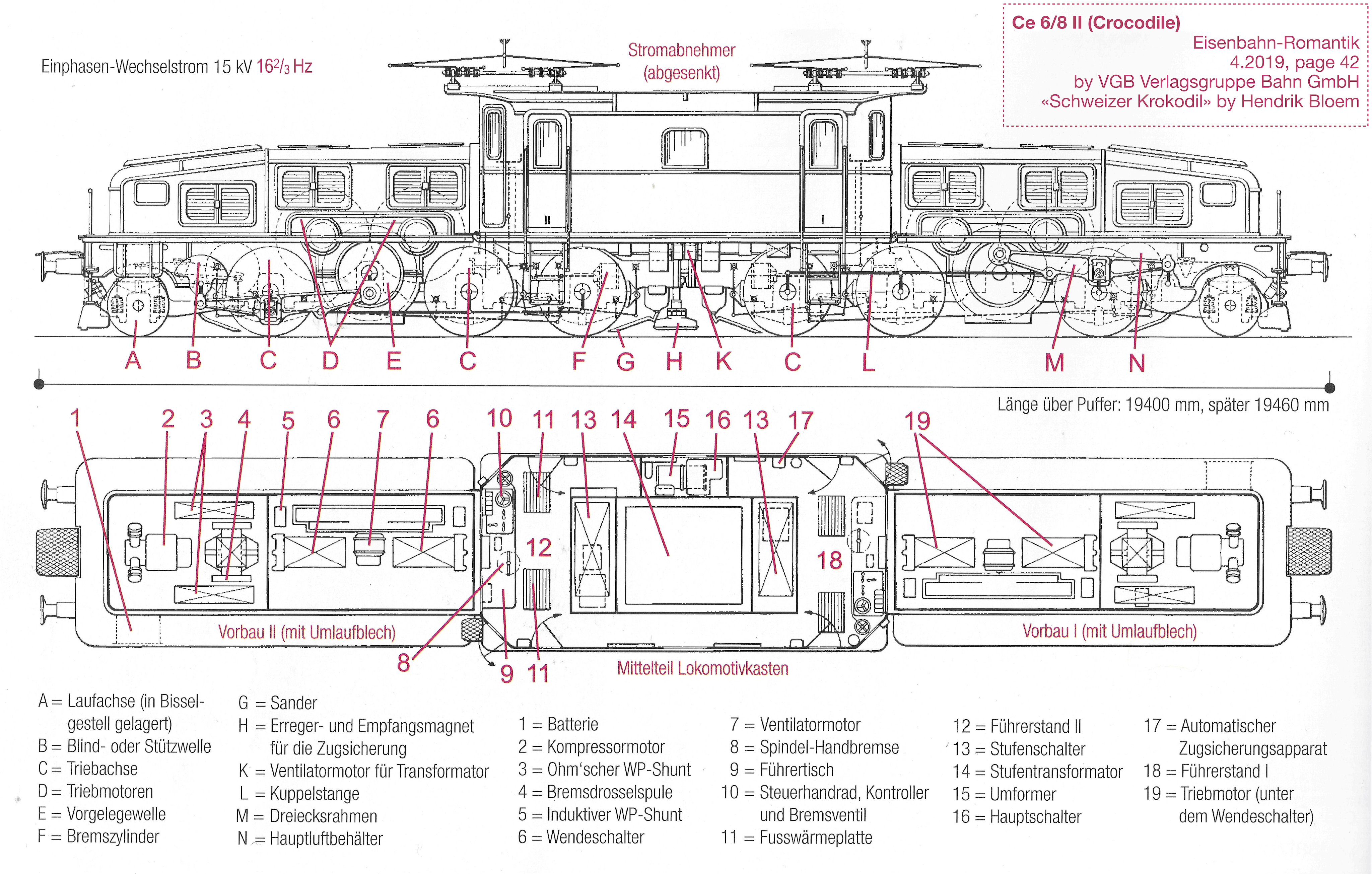
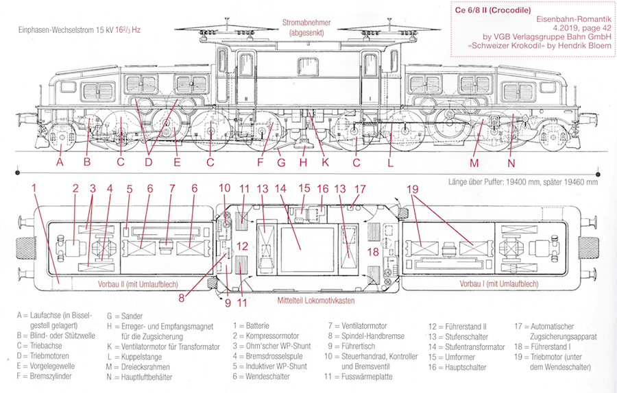
Fig.2b Fig.2b – The II-end is at the left. From Eisenbahn-Romantik, 4.2019, page 42 by VGB Verlagsgruppe Bahn GmbH «Schweizer Krokodil» by Hendrik Bloem. Download PDF (4 MB, here) and JPG (4096, 900). Scanned from magazine and published here by permission from VGB Verlagsgruppe Bahn GmbH, 9Feb2020
I have actually found no sectional drawings of the Ce 6/8 II or III on the web. This drawing is from [1]. Thanks to VGB! I have not translated the German text. However, in [2] there would be even some cross sectional drawings, on two double pages.
Aside: I scanned as 1200 dpi and filtered some, then made a searchable PDF in ABBYY FineReaderExpress. But I found no font that had it convert Bloem correctly (it was always ‘i’ instead of the ‘l’), so imported that PDF into Pages and wrote the boxed text there (plus fixed 50/3 to 16⅔ instead of 16,7 Hz or 16.7 Hz (*)) and exported as PDF. It is still searchable. I also converted that PDF to 4096 and 900 pixels JPG. (*) 16.7 Hz is correct after 1995 (see Wikipedia’s 15 kV AC railway electrification) – so my change may have been wrong!
Electrical drawings
I have now bought a scan of the two best circuit diagrams (Schaltplan) that SBB Historic has. They are as nice that I could cry! See SBB Historic: Schaltplan – two circuit diagrams of the Ce 6/8 III crocodile.
Märklin 55681
This is a beautiful and very well designed and produced model. A joy to own! I enjoy every second! The label underneath says märklin 19045206 C€. Plus there is the märklin which is part of the metal frame.
Handling
How to lift it

From the 55681 manual [8]. IMPORTANT!
Not upside down with roof in place!

Made from the 55681 manual [8]. IMPORTANT! Press for PDF to print out
I was very unwise and wanted to have a curious look underneath – without thinking! The roof fell off! Luckily for me it hit the wooden floor from a low height, softly, and only a corner mesh fell off. It was easy to put back in place, there were three holes and pins. I also added a tiny drop of glue. Not visible from any angle, not even with the root off. The wire and connector were also pulled out, but nothing bad happened! I made the picture from several pages in the manual [8]. Press for a PDF to print out.
Disclaimer: (Not that it matters, since the roof did fall off). I may have been very unlucky and pushed the roof by accidence, in some way that I am not able to (or want to) reproduce. It may be that Märklin indeed has selected strong enough magnets, technically speaking. I tried to lift the roof with a luggage scale. It came off around some 500 g lift, on each side. 1 kg for both. The magnets also hold some after they slip. The weight of the roof is about 540 g. So it should be enough! Anyway, remove the top! It’s best in the long run!
How I carry it
However, even carrying the loco like that for two meters is tough on the fingers. So I made a veneer base and screwed a 60 cm track on it. And after the topmost picture was shot I made it thinner and easier to grip at the ends. Also good for the first lift off the table. The base that came in the box is probably not too well suitable for this.

Fig.3 – Märklin 55681 Ce 6/8 III carrying railplate, Øyvind Teig (press for more pixels)
Upside down on the workbench
Attention: If you have placed an extra driver inside cabin II, observe that he may fall out! Mine (here) actually stayed in his bindings, and the plate he’s mounted on didn’t move either.
I always keep everything that passes by, of the type of styrofoam that doesn’t disintegrate by a pinch; the type where nothing would fall off. Before the woollen seat pads, that plastic, you know. It’s expensive to buy, and for the environment it’s better to reuse than to have the factories produce more of the nice and terrible stuff. When my box gets full, only then do I return as plastic waste, the smallest pieces, or those that are glued the most. It was in that box that I found the material for different bases I needed for my upside down 55681 exercise. (By the way, this is also nice for turning HO/H0 locomotives upside down. Just make a kind of negative imprint of the loco box and cut out more for the delicate parts.) (Some more on materials here: My materials science notes.)

Fig.39 – Styrofoam bases for the Märklin 55681
First, read all the words here. Only then start to lift things.
Second, make two bases for the roof. And find a small pair of pliers.
Then lift the roof off by pressing the fingers against the motor side tops, and up. It takes some pressing before the four magnets let go. Then hold the roof with one hand and use the pair of pliers to carefully loosen the servo cable’s connector. I found it easiest to loosen the part in the locomotive.
Check that all four magnets are still in the center box in the locomotive. If not, see «Some loose parts» (below).
Then make four styrofoam pieces for the body and two thinner ones for the center box. They should have some height comparison with each other, of course. Place them on the table, apart, to avoid placing the yellow signs on them. Then psyche yourself up, because you need two hands that takes a twist. Lift and twist. Then carefully place the loco down on the six styrofoam bases. I guess that’s about it.
Aside: don’t loosen the center box! I wanted to find out whether I could loosen the center box, so that I later could fit the driver in direction II (see Driver in direction II and a ground personnel) by letting the driver’s cab open from the top. Don’t even think about it, if that is the only thing you want! I think each and every screw underneath, not only the four recessed screws, would need to be loosened. And then you would get the problem of dismantling the handles by the steps, not a good idea. Not alone push them in again. Again see «Some loose parts» (below). Let them be like they are. Besides, I found a much better solution to placing my driver inside the empty cab. Again, it’s in Driver in direction II and a ground personnel).
Fig.38 – All the six wheels are loose in «suspension chambers» (no sound)
When we spend so much money on a single piece, it’s only natural to be curious and to turn it upside down, just to enjoy. Most of it is metal, but there certainly also are plastic parts. So, be careful. Now, run the movie and enjoy the nice suspension!
Update 26Jul2021: I have learned from the magazine Faszination Spur 1 #17 where Peter Pernsteiner goes through the Märklin 55526 of SBB Ce 6/8 I #14201 (here) that some times plastic is considered a better choice. On that locomotive the extensive cooling tubes along the sides are made of plastic since making them from metal would faster have worn the sides and made them not so nice, for the view of them. Fair enough!
Crash to safety?
I experienced a CRASH on my shelf! Believe it or not! Here’s what happened. I got excited and turned the accelerator up, with a plan to enjoy the squealing noise from the brakes. Playing like a child, that is. Blush. (But that squealing does have at least three CV registers: 64, 163 and 164, plus the f9 function. But that’s for more adult children. Unblush). All of a sudden I saw that the loco did not obey my stop command! Then I discovered that the MS2 (Mobile Station 2) was restarting! The loco went straight into the rail buffer and continued with rotating wheels on the dry rail! Terrible! Finally I got contact with it, and it decided to stop pushing against the Märklin 5602 buffer. But luckily, everything survived – with no new pieces and no spare pieces to order!

Fig.21 – Felt pads added to buffer and cable ties cables! (press for more pixels)
First, I should have used the central, round RED BUTTON that changes direction, in order TO STOP. The built-in power capacitor (called a voltage buffer in the manual [11], but this is an electric charge buffer) (set by registers to be connected) causes the loco not to obey the standard, wide STOP STOP button. The loco simply runs on over bumps and dips of no voltage on the line, so removing power of course won’t stop it. That’s why the battery capacitor is there. I am so used to it stopping that I had forgotten! It’s my reflex to this kind of situation, built up over several years: press the STOP STOP button. I have to unlearn it. Especially since it also works for my other MS2, the one that controls the H0 /HO models.
Next remedy was to add two felt pads (maybe not felt, this type has more elasticity to them, more like cushions or rubber) on each buffer plate. Press picture and zoom in. It would hopefully absorb some energy should any next time happen.
Then, even if I have experienced software crashes and restarts with version 3.55 of MS2 (but only on my HO layout, with protocols mixed), I think the problem here was that I had gotten so eager that I pulled the cable too much and the MS2 was unpowered for a short period. (But it changed language..) I could see the cables just getting in contact. (Which might explain the language change..) So I made a backplane for it and fastened the cables with cable ties. See picture. Update 1Nov2020: I have seen one language change (back to German) and one run-wild uncontrolled situation (but thanks to the remedies below, with no consequence whatsoever) also after this change. No bad contact, that is. It’s something with the SW/HW of the MM2.
Setting Vmax
I then set lower max speed (to 40), lower acceleration delay (to 3) and and lower brake delay (to 3). Now I have more direct control with the loco, and it can’t speed up too much for any worst case buffer bumps. Here’s how:
-
- I am using a mains switch in the power supply to the rail box. I have described this in note 132 (here). This way I think the firmware of the MS2 is not (so often?) destroyed beyond update from another MS2 (in which case it has to go to Märklin service in Germany). The switch is seen in the picture here as well
- I let the MS2 stand «on» the locomotive and inserted its loco card. This reads the card and replaces any data set in the MS2
- CV 03 acceleration delay and CV 04 breaking delay I set the easiest way (method 1 (named by me)). Change loco, Acc – Dec etc. I set both values to 3, after experimenting some
- CV 05 maximum speed I was not not able to set by method 1 (well, it looked like it did, but the loco did not seem to accept it). Therefore I did method 2: Program CV, which causes it to read the Mfx registers etc. Motor, Speed, Vmax. This worked, and I set it to 40. However, for some reason method 1 had not caught up with the value. I wish I had been responsible for that software. I wouldn’t have been satisfied with this
- I then wrote to the loco card
Tacho value
By the way, what is the tacho value of method 2 (above)? It’s displayed as value 75. Does it have anything to do with the discussed Ticking? I cannot find anything about it in any of the documents [8], [11] or [26]
Setting direction

Fig.5 – MS2 arrows fit Märklin 55681 direction with DCC CV 29 BIT0 set accordingly. Photo Øyvind Teig (press for more pixels)
(Search: «SET-DCC-CV»). The arrows on the MS2 and the loco direction were opposite! And I did not want to turn the loco around, because (1) I wanted to see the driver in the I end, and (2) I want to see the electrical wires on the top – from where I normally stand. See märklin-users.net point 3, which is where I got the hint, here is how I did it:
- Starting with the loco registered as mfx+ and having a copy of its setup on an (orig) loco card
- I set the protocol to DCC only
- I deleted the loco
- I added a «Kroki DCC3» as my new loco, with address 3
- I changed CV address 29 value 0x06(=6) to 0x07(=7) to have the direction BIT0 set
- It worked, the arrows on the MS2 now point in the same direction as my loco on my 2 m. shelf track
- I saved the loco to another loco card
- I deleted the loco again, since I did not want to set all the icons etc.
- I added the loco back again from the (orig) mfx loco card
- I changed the protocol to all three: mfx,DCC,MM2
- The loco now runs mfx and the arrows on the MS2 are ok!
This is about the same procedure as How to set register CV 50 to value 8 with MS2 in note 132.
However, this may also be done when the loco is configured. This is explained in the 60657 MS2 booklet: Mobile Station 2 (version 3.55 or higher):
- P17: The following selection is only for locomotives with DCC decoders
- P18: Programming a Locomotive (CV)
Trivia
- «scale 1» = «1 scale» = «gauge 1» = «1 gauge» = «gauge one» ≈ 1/32 with..
- ..gauge = 44.45 mm → 45.0 mm Märklin, like 59059 (?)
Listed (1-5)
- When I had unboxed it and was going to clean up in the box, I found a loose plastic piece with a Swiss cross. It turned out to have fallen off the one of the joints of a rod. It was the cup, the one in the lower middle on the third driving axle of fig.1. I just pressed it in place, but I heard no click. So I must be observant in the future
- The wheels are driven through the external rods, no gears on the drive wheels, and one electrical motor in each bogie.
* At very low speed (creep range, close to stop or start, like when going from the last step to stop or from stop to the first step) the rotation is somewhat irregular and choppy. I think I heard said on the German language DVD accompanying [1] that the Ce 6/8 locos were famous for the sound of the rods, that they were somewhat loose in the joints. (Update: I have now discussed this more, see above). They certainly are somewhat loose on the model, so this is only natural. I have not changed the number of speed levels and the minimum speed in my Mobile Station 2. They are at default - Even though the very large proportion of pieces are of metal (mostly die-cast zinc, with some smaller parts from brass ([19], Longimanus), some are of plastic. Like the sanding tubes, and the inside of the doors. All the breaking arrangements as well. Plus the «excitation and reception magnets for train protection» at the center of the unit. (See Train protection systems Integra-Signum and ETM-S in this note). I guess this is just as good, plastic would not break as easily as cast metal. Also, the boards to walk on, on the top, appear to be plastic. The flexible cables connecting the parts, two sets on each side, are rubber or something very flexible. See my question at markin-users.net, here. My buying of the loco was dependent on exactly that answer
- Observe that the metal alloy is not magnetic, so it’s not possible to use a magnet to check what is what
Ticking
- The f30 sound is the «Speedometer (ticking)«. How does it work? It also ticks when the loco is standing still. See question 5 on marklin-users.net which you should read before this. I have also asked on Norwegian nmjforum.no at Mekanisk speedometer/tachometer anno 1920:
* I have recorded and measured the ticking. There is a distinct tick every 0.495.. second. I assume that is meant to be 0.500 second, but the clock in the loco which they recorded from may not have been tuned that accurately. Between this tick there are two smaller ticks, so we have three intervals. At 36 km/h anything moves 10 m per second (36000 m / 3600 seconds), 5 m over half a second. This is a little more than a revolution. The main wheel has a diameter (⌀) of 1.35 m, so it would move 1,35 * π = 4.24 m in a revolution. If the speedometer is being kicked once per revolution per second it should show 36 km/h * (4.24/10 ) = 15.26 km/h. Thus with a fast «up» / slow «down» arrow to integrate over this length it should show about 15 km/h. If the speedometer is a wound clock I assume the ticking is to clear the integration, hold the arrow or something like that. In that case it would tick while there is a stand still. Plus it should then show zero, to be verified by the driver.
* I found in [2] (p.20) that the speedometer of Ce 6/8 II was indeed Systems Hasler type. This was also suggested here:
* From question 5 on marklin-users.net there’s more (there may be more at the source):
Me: «I have been thinking, maybe the ticking at stand-still might be from a paper logging mechanism? I read that the clock logged events on paper from the Integra-Signum safety system.»Unholz: «Oh yes, this is certainly true. I remember the recording paper rolls in the Hasler speedometers from my youth when it was still easily possible to sit next to the driver/engineer or behind him in some SBB railcar types (namely the «Red Arrows», the BDe 4/4 and RBe 4/4). The paper had to be exchanged from time to time. I don’t remember whether this was after every driver shift change or when the direction changed or simply when the registration paper was full.
BTW, the registration paper was always removed and confiscated by the police immediately after every accident or derailment because it contained the necessary information about the speed of the train.»
Tom Jessop: «The Hasler recorders used a roll of waxed paper which recorded speed, engine notch position (speed setting), brake pipe pressure and brake operation, use of whistle, vigilance (dead man’s pedal) operation & something else which I cannot remember. Air pressure from different sensors then caused needles to operate across the waxed paper. A roll of paper would possibly last a month or more depending on locomotive use, the roll would be checked each time the engine would be prepped & if the tell tail on the tape was showing a fitter would be advised to come & put a new on in the recorder. Although a speedo is in every cab only one would have the tape facility mounted in it. This is only for double ended engines.»
* Worth reading is the Speedometer article at Wikipedia, but it did not make me any wiser in this regard. Or maybe even more interesting are the Tachometer or Wheel speed sensor articles. But to me, still unsolved how this one would work.
* I also discovered a Tacho value. What is it?
Speedometer with clock
 Maybe the final solution is as simple as this? The picture here is taken from an article in the Neue Zürcher Zeitung [23] and shows the speedometer with 24-hour dial in the 14253. Of course this clock ticks! This is the first picture I have seen of it. In retrospect, in all but one of the other references up to [23] I cannot find it. Not even on those from the newer cabin, like the double page picture of the 14253 (page 34-35) in [2]. The reason is simple. On the picture from [23] there is a different speedometer! It simply does not have a clock. Looking over the movie that came with the [1] DVD (example at 1.20.04) the clocked speedometer is seen in the 45 degrees right side window.
Update 15Jun2020: There also are two great pictures at [24] (Cab rides, Führerstandsfahrten by SBB Historic). See picture 3 and 5 of the 14305 series. Also, picture 3 shows the cabin in wide screen. And picture 5 shows the bottom text of the instrument:
HASLER A. - G. BERN
VORM. TELEGRAPHENWERKSTÄTTE VON G. HASLER
Speedometer without clock

Märklin 55681 (iPhone Xr: Magnifier app)
And the Märklin 55681 cabin of the 14305 has a speedometer just like on the picture in [23] – without any clock! Is this also just a left out detail (like the dead man’s pedal, below)?
So there still is a mystery: what ticks, then? Is it still the paper logging mechanism?
From which locomotive is the soundtrack of the Märklin 55681? 14253 of 14305 or even 13302?
Clock & speedometer with recorder on the top

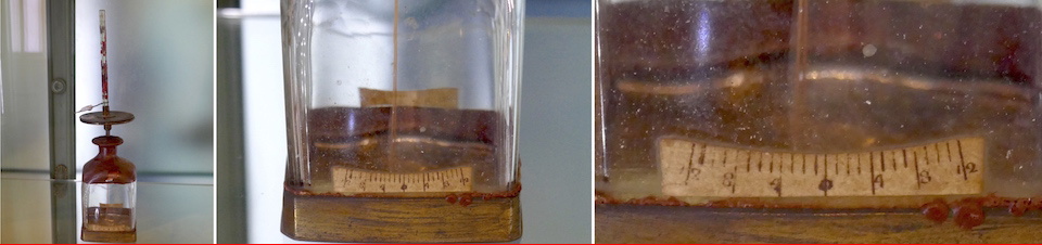
Some Crodile (about 2005), [12] p79 (Photo Ralph Schorno, excerpt)

Details of speedometer of SBB Ce 6/8 from magazine photos. Left: (1930?) [2] p17 SBB. Center: Ce 6/8 III [1] p47 2019? Eckert? Right: 14305 [1] p41 2019? Bloem
There are more photos of the speedometer box. I have collected all of the others I have in July 2020. One from about 1930 and two from 2019, I assume. Those from 2019 may be from 2000 for all I know, but they are of newer date. On the center picture the top box is gone. Is it being serviced or has it been removed for good?
Aside: I scanned these pictures at 1200 dpi. All of the rasterisation from the printing process was visible. Not nice to show. I tried all the filters I had, but since I was only going to get my point across, pixels were not so important, but some clarity was. And they are anyhow owned by the photographers, so I must be careful about copyright. (But every time I ask I get a «go on», so I assume it’s ok.) I scaled down to 900 and lost much of the picture. And then up to 1800. Quite a nice home made filter to remove at least som rasterisation. Scanning at 100, 300 or 600 dpi in the first place did not do the trick. I did not end up with as nice(?) pictures as these. Even if it they are not there for the pixels, it doesn’t hurt that I honour the originals.
Time off for a picture

Fig.18 – Just lovely!
Listed (6..)
- After some time I discovered that a cable at the roof was not in position. This is visible in Fig.1 (right door, left handle then up, the purple cable end). The photo is not in focus there. When I moved it slowly with my fingers I was able to press the cable up and into its two fastening holes. I am 90% certain that this was as arriving in the box
- The labels on the servos for the pantograph don’t stick! Lift off the roof to see. I made new paper labels that I fastened with double-sided tape that I know stick. And stored the original stickers. If you want to do the same, print out this PDF
- The layout of the two central fan frame blinds may not be as prototypical as they could have been. Disclaimer about this: I am quite unsure! See note 203: Fig.1 aside
- Spring-loaded axles
* On the Märklin 55681 with the three driven axles on each end part, the central axle only is spring-loaded. This makes 90% sense. Passing over a bump – that axle will be pushed up. Passing a dip it will be pressed down. But the two other axles on that bogie might, on bad track, be pressed up from the track, since they don’t follow. However, even if the model costs a lot, spring-loading all the three driving axles would have added cost. I am ok with not having to carry that extra sum, and instead keep my track from becoming bad. It looks like the 55681 certainly runs very smooth. More: it is a dream come true to hear, feel and see it run! Even without engine sound
* This is somewhat different from the Ae 3/6 II HO Lemaco model I have, which is spring loaded on all three powered axles. In this case the locomotive probably will follow coarser track better than my 55681. For the Lemaco, see SBB Ae 3/6 II (Spring-loaded Lemaco model)
* The two pilot/leading wheels in each end are of course spring loaded on the model
* The real locomotive has leaf springs on all axles, even an intricate system with some springs being interconnected. When I turned my 55681 upside down, to see if this were modelled (when the top fell off!) I could see that Märklin seems to have modelled the complete spring system. Have a look at the beautiful pictures in [19] by Longimanus - All the 18 Ce 6/ III were originally painted in brown colour and black chassis ([2] p.61). When was the #14305 (and #13302) painted in the fir-green SBB standard color and with gray-colored bases and drive parts?
- 55681 has no traction tires, and they are not needed. Much nicer without them!
- I have not found any materials and an exploded drawing of the 55681. There are some necessary drawings in the manual that comes in the box [8]. Would have been very nice to see them!
- Since the Märklin 55618 is revision
02.11.17(2017) the colour (color) scheme should be as the original was at that time. Tinu (24Jul2019) [19] mentions that Märklin shall have stated that it is painted as it was on date of issue (2019), where the real handrails are black. But they were, according to Tinu yellow before they were painted black, in Jan2018. Consequently they were in fact yellow, as on the model, on the printed revision date02.11.17. However, I would assume that when he says that the main green is not 100%, that might be correct. Because the green does not seem to have been painted in Jan2018 - I got this in a mail from a German friend, talking about the new Märklin scale 1 models (KM1 = KM-1 = KM-1):
«Märklin went with the production from Hungary to China and choose the producer of KM1. So they have absolute new know how and cheaper prices. The new models by Märklin look same as Kiss or KM1. But they are mostly die cast, which is not bad for players.»
What applies to the 55681? I have not spotted any «Made in ..» on the model, box or in any manual - The nicest picture you will find of the 55681 is on the box! However, it is only the right side of the loco (when end
Iis ahead). I think the two pictures on the longer sides (52.6mm long buffer-buffer) are the correct ones. The one on the long top is a little pressed down, so it looks a little flatter than it is (I think). There also is a similar, small one at one end. I think it’s ok. Märklin must have had both sides of the loco photographed? In case, why didn’t they print both? And why did they print the least sexy side, with so few cables on the roof seen? Ask me, who only realised the same point after my wife shot the picture!
Rods, axles and ends
(Thanks, Eiler, for trigging me on these points!)
Rod placements

Fig.15 – Märklin 55681 rod placements
On my model, in both end I and end II, it looks like the rod placements are about 87° out of angle, one side of the locomotive with respect to the other side.
In the figure I have measured the angles from zero in the running/rotating directions “ahead” and “reverse”. I run ahead (white graphics) in the I direction and reverse (yellow graphics) in the II direction. There are 13 spikes, so each angle spans a «spike angle» of 360°/13 ≈ 27.69°. For the front end I I got 87.8° displacement. For the back end II I got 86.5° displacement. Like about 87°. But it’s not very accurate. If this should have been 90°, below is what 3° looks like. Yes, I may have been that wrong!
![]()
I don’t see that 87° coincides with spike angle or multiples of it, like 27.69° * 3 ≈ 83.08°. Maybe it’s more a function of the internal gear construction in the Märklin model?
How is this on the real Ce 6/8 III #14305? Will the rod placement angle have any significance on how smoothly the locomotive runs?
Axles

fig.14 Ce 6/8 II assembly at SLM Winterthur 1920 (detail) photo MFO
All the eight axles have their two wheels shrunk on them. Therefore two wheels and their axle are one part. As we have discussed a lot, the driving wheels on each side have rods connect their three wheels with the countershaft («Vorgelegewelle»).
Two motors are paralleled. Each just have to have a through-going axle. We can actually see them on the outside: the two half moons. On each end of the axle there is a small cogwheel connected to the larger cogwheel on the countershaft. This forms a gear on each side with a 4.03 : 1 ratio. So there would be four such gears on the locomotive.
I am not certain whether the countershafts have a single connecting axle or if they are alone on each side. I only found one picture out of all the ones I have (scanned from [2] p.19 and cropped to a small fraction only). Speculating (seen in the picture as red), I think I can see that there is an axle between the countershafts: a common countershaft axle and a gear on each side. So «everything» seems to be mechanically paralleled. This is something that everybody that knows just a little about this would know. Help!
I am not certain whether the below indicates the opposite, that the countershaft gears are held in place «locally», with no connection to the other side. See [2], page 16:
| Die Bewegung wird auf die im Rahmen fest gelagerte Vorgelegewelle mittels beidseitig angeordneter Zahnräder in einfacher Übersetzung von 4,03 : 1 übertragen. | The movement is transmitted to the countershaft fixed in the frame by means of gearwheels arranged on both sides in a simple ratio of 4.03: 1. |
By the way, the Coupling rod, Jackshaft and Stangenantrieb articles are interesting, see Wiki-refs.
Ends
There is no mechanical connection between end I and end II, no synchronisation. Even if all four motors are powered from the same transformer with the same step and all four motors are AC single-phase motors. (See SBB Historic: Schaltplan – two circuit diagrams of the Ce 6/8 III crocodile.) Speculating again, having them synchronised would make pulling less efficient. If one bogie’s wheel-set were to slide, the other bogie’s wheels could take over.
Artefact sound?
Update: I also hear this sound of a phantom raising of a pantograph if the f30 speedomer ticking is activate when the loco gets power for the first time. Before this activate f30 only and unpower and wait until the power bank is empty and it stops ticking.
Strange artefact sound on first start-up. Listen to it here. There is one strange sound (?), a start, a stop and a start again:
The sound file is downloadable from here. I recorded it on an iPhone.
When I repeat start-up (operating sound: f2) and turn off and new start-up I don’t hear the strange sound that comes before the first f2. When i press the STOP button on my MS2 and wait some seconds and power the line again, and then a new f2 to start, this artefact of a sound comes. Have Märklin hit the wrong seconds tag on the sound file? (If that is how it works).
In the manual f2 is said to be «with random sounds». I assume that the random generator that is used in the firmware is a pseudorandom number generator that starts with the same seed. Then the sequence will be the same for every locomotive, every time. May this artefact sound be a feature from this effect?
I have tried all the sounds available on the loco, and I cannot find that artefact sound. I think it is the sound that comes when raising a pantograph.
I have queried about this at marklin-users.net, point 4 (below).
The original sound file is downloadable from the Sound-/Decoderproject at the 55681 page [9]. It comes down as M55681_Ce6-8-III-Historic_Spur1.mdtp. There is a tool to build these files called mDecoderTool mDT3 [10]. Which decoder does the 55681 have?
Multi-stop station announcements
The 55681 has multi-stop station announcements (on repeated f27), given in sequence (starting on the last used, respection direction change – if the DCC register CV 60 has default value). Here are the 11 stations. They are announced in Swiss, on 3 and 4 especially difficult to understand:
- Erstfeld (60.53 km from start at 475 m above sea level)
- Amsteg
Also called Silenen Amsteg - Gurtnellen
- Wassen
- Göschenen (1109 m)
Gotthard rail tunnel here. 15003 meter long at 1154 m maximum inside, opened in 1882
- Airolo (1144 m)
Ambri Piotta not stopped at
Rodi Fiesso not stopped at - Faido
- Lavorgo
Giornico not stopped at - Bodio
- Biasca
Osognia not stopped at - Bellinzona (169.62 km from start at 244 m)
Driving distance is 109 km and maximum elevation is on the southern side, where it is 910 m. Maximum elevation is 27 ‰. Distances from start is taken from the Timetable of Gotthard Railway from 1899 (GOTTHARDBAHN Fahrplan v.1.October 1899) on Wikipedia (here) referenced in the Gotthard railway article. The heights are from the same article’s figure, Longitudinal profile of Gotthardbahn incl. branchlines. The «not stopped at» info is deducted from table Gotthard Railway Double Track, also in the same article.
Q1. I don’t know why 55681 does not stop on all stations. Maybe a limit to the size of the sound file or didn’t the original stop on them? Here it the answer from SBB Historic’s JC, when I asked:
I must admit that I do find the multi-stop announcements a bit confusing – seeing how the Ce 6/8s were built as freight locomotives, it makes little sense for them to have stop announcements.
In the mid-fifties, when their designation changed from Ce to Be (meaning it had a higher maximum speed and was thus also suitable for passenger trains (where it would make sense to actually have announcements)) they did apparently pull some passenger trains over the Gotthard. I did however check with a timetable from Summer 1955, but none of the trains had that exact stop pattern. (Maybe that one is on the sound effect producers?)
Or maybe it boils down to having fun and informing me about some of the stations, of which I have sadly visited none. Like saying: «you should go!» Plus, I guess they do have some museum traffic with passengers these days… So, yes, I should go.
Q2. Also, why do they have a local maximum height inside the tunnel? Maybo so that they in case of power failure always could roll towards one of the ends? Update: wrong! Here is why (thanks, JC):
As to your second question, this is apparently for water drainage reasons (and air circulation)! I have attached a scan from a book on tunnels from 1920 [33], it says «lange Scheiteltunnel unter Gebirgsrücken erhalten aus diesem Grunde meist Fall nach beiden Seiten» (long summit tunnels below mountain ranges usually receive a decline towards both sides), listing the Gotthard as an example.
Train protection systems Integra-Signum and ETM-S
Summary: Integra-Signum unfolds as the excitation and reception magnets, down towards the track, in the middle of these locos. As seen above, the Integra-Signum is Swiss. It was in use from 1933 to 2018. Lately the newer ETM-S system was added, as a simplified version of the newer European ZUB standard. I don’t know if the crocodiles can run on all tracks in Switzerland these days.The «fitnessfahrten» are probably rather local. In the DVD accompanying [1] I think they said something about this, showing another, approved locomotive driving in front. I think that locomotive had ETCS Level 1 Limited Supervision (ETCS) system. Here is my path to this info:
I found this also confirmed in [2], page 45:
| Ab den 1930er Jahren war dank einer neuen Sicherheitssteuerung und der automatischen Zugsicherung die einmännige Bedienung möglich. | From the 1930s, one-man operation was possible thanks to a new safety control system and automatic train protection. |
Is the «new safety control system» the Integra-Signum safety system – that is seen visually by the magnets going down from the Ce 6/8 II and III towards the rails, at the center of the locomotive? Yes! By reading further in [2], page 62 I learn that:
| Die beiden Lokomotiven sind mit dem inzwischen vorgeschriebenen Zugsicherungssystem ETM-S ausgerüstet und gelegentlich vor historischen Zügen in derganzen Schweiz zu sehen. | The two locomotives are equipped with the now mandatory train protection system ETM-S and can occasionally be seen in front of historical trains throughout Switzerland. |
That text is in a chapter about the III-version locos. Therefore the two locomotives referred to are the two green coloured locos (1-2). Did the brown II-version (3) also get ETM-S added to its original Integra-Signum system?
Then, in the German Wikipedia article about Integra-Signum (chapter Euro-Signum) I read:
| Zum Lesen der Euro-Signum- und Euro-ZUB-Telegramme wurden bis 2005[3] die Streckentriebfahrzeuge mit einem speziellen Zusatzgerät, dem Eurobalise Transmission Module (ETM) ausgerüstet. Das ETM, umgangssprachlich auch „Rucksack“ genannt, leitet die Informationen an die Integra-Signum- und ZUB-Fahrzeuggeräte weiter.
Zunächst waren noch etwa 400 Fahrzeuge des Rangier- und Baudienstes von der Umrüstung ausgenommen.[3] Fahrzeuge des Rangier- und Baudienstes oder historische Fahrzeuge, die nicht mit ZUB ausgerüstet werden mussten, wurden bis 2011 mit dem vereinfachten ETM-S ausgerüstet, das sich auf die Integra-Signum-Funktionen beschränkte. |
Up to 2005, the mainline vehicles were equipped with a special additional device, the Eurobalise Transmission Module (ETM), for reading the Euro Signum and Euro ZUB telegrams. The ETM, also known colloquially as «backpack», forwards the information to the Integra Signum and ZUB vehicle devices.
Initially about 400 shunting and construction vehicles were excluded from the retrofitting. [3] Shunting and construction vehicles or historical vehicles that did not have to be equipped with ZUB were equipped with the simplified ETM-S until 2011, which was limited to the Integra Signum functions. |

Vehicles that were not equipped with ZUB were equipped with the simplified ETM-S. Von Plutowiki – Eigenes Werk, CC BY-SA 3.0, Link
«An Eurobalise is a specific variant of a balise being a transponder placed between the rails of a railway.» See Wiki-refs.
From the German Wikipedia figure we can see the Integra-Signum magnets. See Wiki-refs, both German and its translation, and the English version of Integra-Signum articles.
Driver in direction II and a ground personnel
Also see:
- 229:[Fitting the drivers] – of the Fine Models E71
- 216:[Height of scale 1 figures]
The 55681 model is not really sold as being able to drive more than ahead in the end I direction, is it? Reason: there is no extra driver in the end II cab! I intended to fill it with a driver, but it wasn’t as easy as I had thought.
Googling and then mailing around, I finally ended up with two choices. I ended up with both. I thought that i did not not want the spare lokführer Märklin E320244 that’s already driving in the I direction. Two reasons. I didn’t want them to look like identical twin brothers and I wanted to be able to open the door fully inwards. Märklin sent me a E602430 as a Christmas gift or whatever (thanks!) (the only exception so far to my Standard disclaimer), but it would have to wave his right arm out of the window (which would have been nice!). Since that’s not possible he was transformed to become my first ground personnel!
Fine Models insisted that I got a Swiss driver! I’m not sure if the one they found for me has a part number. He wasn’t really able to do the driving with his hands on the controls, but as seen from the outside it’s more than good enough!
The two men would have been about 160 cm and 167 cm tall. The head space in the cabin is about 58.5 mm * 32 = 187 cm. The door opening is 54 mm * 32 = 173 cm. When the men are seen compared to the locomotive it’s striking how huge the loco is! I’m looking forwards to seeing it some day!

Fig.36 – Mounting of loco’s end II driver plus ground personnel (Fine Models and Märklin E602430)
The built-in man probably is glued in place. And the door does not fully open. I reckon that it’s like this in the real cab: it’s not a dancing floor. At the beginning I tried to find out how to remove the center box, so it would be easier to fit the driver down from the top. (It’s in Don’t loosen the center box (above)). None of my drivers have been glued in place. Quoting myself from the E71 note: «Yes I know, the fitted driver on the Märklin 55681 is glued to the floor. But none of those drivers fitted by me will be glued. What happens when somebody is just a little too curious – with the floor? I couldn’t bear the thought of it.»
I ended up with keyhole surgery, or rather zero invasive surgery, and tweezers (with plastic on the tips!). I decided not to glue it there. I wouldn’t want to (later) make scars on the floor and I assumed that if the door were to be opened, some small fingers may just go in there for an innocent check. «Oops!!»
 To keep the door held open during all of this process I took some dental floss, a piece of soft plastic, bored a hole in it, and fastened it to the end. Then sowed the floss through the opening to the left, with the door open, the floss all the way alomst to the other door, there’s detail there that it can hang on and then down, with something soft pulling it down (the yellow piece in the picture). The piece at the end, inside the cabin, holds the door open.
I ended up, for the figures, with a plate to stand on. First cut from a tin box, but I didn’t like the appearance. I found a nice copper plate with glass fibre plastic inside. It’s 0.5 mm thick and it’s noted BENDFLEX on it, from the guys I once worked with at production at Autronica. Perfect! I made two straps of some 0.65 mm copper wire, bored holes and soldered them on. The size of the plate is 15 * 26 mm, and it must first be placed in the lower left corner and then slipped down towards the control desk. In Fig.36, see the small piece in front where I cut out a part, to make it pass the handle of the control desk. I made two such plates, because the hands at first collided with the desk. But the second around (actually the third) was fast finished.
I made some grooves in the plate to make it look like planks and painted it some (bad match, only seen when the door is opened, though).
Now I inserted the plate carefully, then slipped the man in and pushed his left foot first into its strap, then the right foot. This can be dismantled about as easily, with right foot first, even if I put half a drop of paper glue behind one shoe. The man stands quite sturdy in there. He’s loose, but still seems to sit stand quite in place.
Maybe Märklin should have supplied a driver for the end II direction, with the door also to be possible to open? He’d have to have a long right arm or do something else on the control desk. Like mine.. I’m sure they could find a smart solution for people to be able to insert themselves..?

Fig.35 – HALT!
Update 26Jul2021: I found that ASOA [34] carry a lot of figures! Like, search for «Krokodil» there.
Limits to miniaturization
Following up the chapter about the fact that there is no dead man’s floor pedal on my Märklin 55681, this chapter is relevant only as seen from a more general angle. Which is how I meant it in the first place. Here is my suggestion of an answer of why Märklin may have dropped it. It is still a model. Not the real thing. The window wipers don’t move, even with the f29 wipers sound on. There is no sand in the sand boxes, and the tubes from the sand boxes aren’t tubes. So what? Again, it’s a model. Scaling things down is about reducing size, how to do it, what to let go and what to keep. Some detail may have been scaled down 32 to 1 if that made them visible enough, or sturdy enough. Some may have been scaled down a little less, some much more, so much that that they are gone from the model. But they scaled the cabin. What the cabin is. And from the outside, a dead man’s pedal wouldn’t really add much. Maybe it was never even decided by the company, but maybe it was a decision done inside a single head; nobody thought any more about it. Maybe ten years before this model, for another model, with another level of detail. Then that piece was reused. It wouldn’t have been very expensive to change or add it at this point in time. But even then the driver still cannot die. He is still a model. On the other side: I can. And I will enjoy this model for my forever. It is not impossible to scale down everything. That’s just how it is.
Problems
Dead man’s foot pedal
Update Jan2024. The newer Märklin 55683 (search for it here) has got the «Dead Man’s Switch» in place! Thanks Märklin!

Fig.4 – Driver’s cab in 1920 (MFO), Märklin 55681: Ce 6/8 III, 14305 SBB Historic, rev. 02.11.17. Photo: Øyvind Teig (iPhone Xr: Magnifier app). Right: the loco in Olten on 19.02.20. Photo: Justin Comps, SBB Historic (press for more pixels)
There is no dead man’s foot pedal on the floor, inside the cab. (So, on my small loco, no vigilance operation. Thanks, Tom Jessop at marklin-users.net, point 5, below). I discovered the discrepancy when watching the fantastic DVD that came with [1]. The pedal is also seen on #14305 (2011) in a picture on page 44 of [2]. At first I thought that the pedal had been removed on the revision 02.11.17, which is the Märklin 55681. Maybe it was not needed any more, when more safety (of some kind) had been added? I mailed SBB Historic and I got the picture to the right (above) back. Thanks a lot! #14305 right now! I added some light to the floor part where the pedal is, just below the black protection shelf, so the pedal may be easily seen. Märklin has not replicated the pedal for the 55681.
Here’s more to the story. [JC] of SBB Historic, told in a mail that she had discovered (referring to the rightmost picture (above)):
«a picture of the cabin from 1920 in the book «Krokodil: Königin der Elektrolokomotiven» [12]. There was no dead man’s foot pedal! The text beneath the picture says «The working space of the Kroki-driver, as pictured in a publication of the Maschinenfabrik Oerlikon 1920». The dead man’s pedal was not built in from the start – it was only added in the 30ies – according to the author of [12]. However it was on 15Jul1920 that the RhB (Rhätische Bahn, another Swiss rail company) decided to go from two drivers in the cabin to one, and then introduced the dead man’s pedal in their locomotives [13]. Their locos were also built by SLM (Maschinenfabrik Winterthur, for the mechanical parts) and MFO (Maschinenfabrik Oerlikon, for the electrical parts) – just like the SBB Ce 6/8 II and III. It then looks like the SBB must have kept two drivers in those locomotives for another some 10 years.»
Nearly no reuse of 55564 parts on 55681
I therefore speculated (wrongly, see below) that the faulty (but forgivable!?) cabin in my (1) 2019/2020 model of the Märklin 55681, Ce 6/8 III revision 02.11.17 (2017) (colour green), road number 14305 is a reuse of the cabin of the (2) 2013/2014 model of the Märklin 55564, Ce 6/8 II, revision 27.5.29 (1929) (brown), road number 14281. Assuming that there is no dead man’s pedal in the 2013/2014 model. Update: however, according to a mail reply from Märklin I am wrong:
Dear Mr. Teig, 55618 and 55564 are two totally different constructions. So nearly no part from 55564 is used at 55618. All parts are new designed. Sincerely yours, Your Maerklin Customer Service (5May2020)
| Following this logic, there should have been two drivers in the cabin.. | ..but this would also wrong as seen from the outside, since it’s a 02.11.17 revision. |
It’s not only a pedal

Press for full text and transcription. Thanks to SBB Historic!
As this theme develops, more info is coming in. SBB Historic’s [JC] has again responded and sent me some more background information:
«Some speculation on my part as well : Since the RhB is a narrow-gauge railway with a comparatively much smaller route system, they may have tried out the one-driver system earlier.
I tried to find some reference on the one-driver-system at the SBB and found the newspaper clipping you can find attached (Gossauer Zeitung 30.1.1932). (Press picture for full article.)
It’s from January 1932, back when there was still quite a public discussion about the safety of the one-man system. According to this article, the first trials at SBB with just one driver only started in 1926. It further states that at the time it was written the personnel felt negatively about the one-person driving and that there are still routes where two-manning the locomotive is necessary for safety.
So, safety systems where continuously being built into more and more locomotives. This would need definitely more research (and maybe there is a nice reference in one of our books I am simply overlooking…) but it’d be reasonable to assume that until then, the Kroki had two drivers.
Only somehow related, but in the same year a bad collision took place near Lucerne (Wikipedia, translated , where two one-manned trains collided, which then lead to the introduction of a Swiss-wide train protection system, Integra-Signum (Wikipedia, translated).»
For the full text (in Fraktur typeface) and transcription: press the above picture to read (PDF). Thanks to SBB Historic. Just paste the German text directly into Google translation (here). But why not try the Die Deutsche Sprache first? (It’s worth a try!)
The safety aspect goes on in the next chapter, but the Limits to miniaturization chapter discusses just what it says.
Hatches wrongly positioned

Fig.46 – Pair of hatches on the left side wrongly position. Courtesy of Pietro Maria Bellinzona
In July 2024 I received this letter from an Italian:
«I really appreciated your work on the Marklin crocodile but …
are we sure that the hatches (side without the central window) are correct?
Comparing the model with the photos of the real 14305 it doesn’t seem like it!»
Pietro Maria Bellinzona
Thanks for the compliment! I started looking for some symmetry or not symmetry, on the noses or on the central box, but I failed. What did this guy mean? After studying at least ten photos of the 55681 and Crocodiles I understood what Pietro had meant. It is obvious:
On the Märklin scale 1 model the hatches (doors) (some might prefer upper inspection flap / maintenance door) on the central box, on the «left side» (when driving in direction I) of the Ce 6/8 III (not the Ce 6/8 II, where that side has no openings at all), well: these hatches have been placed erroneously «to the left» instead of what would have been correct: «to the right» , as on the original.
To me this was such a revelation that I had to look again, and again. And again. But the proof must be this photo (with a disclaimer below):

Photo by nzsteam, original on flickr, as downloaded to Wikimedia. Text «100 Years of Crocodile Excursion – 19 October 2019«.
Looking over the models listed in the chapter II and III-type versions | Märklin I see that at least the 55688 New York Central Railroad (NYC) model, and 55686 have also got this wrong. I have now queried about this at marklin-users.net, point 10.According to Pietro «the most amazing thing is that the H0 and Z (!) models are right (more or less…)«. Update Dec0204: Since it’s depicted from the bad side, I can now see in the full line catalogue for 2024/2025 p324 that the 55683 also has this fault. But see Comms with Märklin (below), which seems to indicate that all scale 1 models have this error.
Thanks, Pietro! As a thank I placed two 1/32 Piaggio Ape models in the Fig.46 photo, bought on one of our many lovely vacations in Italy.
Disclaimer: The 55681 has revision date 02.11.17 and the above photo of Oct2019 shows the same date, but with a smaller revision (?) done, seen as R2 Mei 02.11.17. These dates are not painted on the same place. I don’t know whether at the same time as the R2 was done, the hatches were also moved. If this is so, this whole chapter fails. Update: older photos, like this from 1926 also shows the hatches «to the right». This disclaimer is void.
By the way, Fig.46 is my first with a new (Jul2024) camera, the Sony DMC-RX100M7 model, after the picture stabilisation mechanism broke on the Panasonic Lumix DMC-TZ100. I had had it for 8 years, and I did lose it on a (wooden) floor the other day. So it was perhaps bound to happen.
Comms with Märklin
My information to Märklin was via email (here).
In a Nov2024 e-mail Märklin told me that the shift is an error no one noticed before production. They are sorry and will correct the issue with the next version of the model.
I have updated in märklin-users.net point 10.
My Märklin

Fig.1 – 1 gauge 1/32 of Märklin 55681 is Ce 6/8 III and 14305 SBB Historic. Photo: Øyvind Teig (Trondheim) (press for more pixels)
My Shelf’s Railway Strip (MSRS) versions
1.0 – 2.0 – 3.0 – 4.0 – 224:[4.1] – 224:[4.2] – 224:[5.0]
MSRS v.1.0
In my dream, the train driver, visible in the picture, is me. He works for My Shelf’s Railway Strip (MSRS). He can take the loco 2 m back and forth on a shelf. Which is infinitively (∞) better than just sitting in a display box or on a roller test track treadmill. The shelf is 2.10 m long. That’s all. No it’s not. Detail: The track has a (1 & 7) 5602 track bumper in each end. The track starts with (2) a straight 60 cm 59059, then (3) a cut-in-two of the same (→ 30 cm), then (4 & 5) two cut-in-two curved track 59076 (r=1.55m, 22.5° → two 11.25°) as an open S’ish. Finally a (6) straight 59059 again. (I also needed four extra rail joiners (8-11) 59095 for this operation. The track is not at all as well reconnect-able as any of the other Märklin track I have seen. Some plastic may easily break.) (See Cutting a curved track (below)). Now the crocodile nicely winds (twists?) itself a little, only to straighten itself a little up again. (Doing it again I might have cut a 59035 (r=1.02m, 22.5°) to get a even more curvature. No, I wouldn’t. Since I wrote that I have received some 59035. Using them would give my grandchildren too little of the needed distraction space in front. More in a sec. (But then, without cutting the arc length of a 59035 is only 101 mm longer than a half 59076.. (lengths below))) It seems like for such a short railway line it’s hard to avoid cutting a full length track in two). Now the train driver certainly is happy, even if he’s facing in the correct direction only on the way back.

Fig.23 – My Shelf’s Railway Strip (MSRS v.1.0) (1/32) (press for more pixels or 20 MB PDF)
The width (depth) of my shelf is 27 cm. However, the outer, some 10 cm, is a a perfect lane for driving cars. Nice distraction space for my 1/32 A-class models and small, graceful, grandchildren’s’ hands. I have never stressed this, they shall also enjoy. I have had nothing to repair after them (or their parents). A width of 17 cm is enough to also include the S’ish shape and catenary (below). A track has width 80 mm (sleepers). My S’ish shape takes up about 41 mm in addition to that. (The length of my S’ish is 604 mm, measured perpendicularly between two imagined walls, one at each end, like «wall» ❷ and ❸ in fig.23.) If I place two catenary masts on each side of the track (95 mm from the center of the mast to center rail, base is 21 * 10 mm) then the half with the masts on the outer side of the track would need 80/2 + 95 + 21/2 = 145.5 mm width, and the other half would need 41 + 80 = 121 mm (less, since those masts are behind the track.) Then you need to add space for the locomotive when it bends out of the track in the curve towards the wall. Some of that space is also used by the catenary mast. I have 24 mm for that. Maximum is then 145.5 + 24 mm = 169.5 mm. Please verify my calculations for yourself, on paper. If the masts are placed like this, no part of the wire will extend past the track’s other side. Another matter, to avoid crashing, I do have some more advice (here).
What would NEM say?
..about the required clear space against the wall in my case? MEM 103 [28] may be the correct standard here? I simply don’t know!
MSRS v.2.0

Fig.25 – My Shelf’s Railway Strip (MSRS v.2.0) (1/32) (press for more pixels or 2.3 MB PDF)
I have made a new layout. I call it My Shelf’s Railway Strip (MSRS) version 2.0. Basically I went for a sharper S’ish by using two ¾ cut 59035 with r=1.02 m instead of two half 59076 with r=1.55 m. I also added an 8 mm 13 ‰ curved elevation to climb to. The full S’ish now is rising. I needed to expand the depth of the shelf so that there still would be ample distraction space for grandchildren to mindfully bring the «extra people» with the 1/32 A-class models from side to side. Observe errata: the blue 160 mm should be 116 mm (see Fig.44).
The Sommerfeldt catenary masts have now been fastened, but I am awaiting some response from them about how to mount the wires. See Catenary system (below).
Picture will come when the catenary has been mounted.
My Marklin (Hübner) track
Also some about this in note 132 at Scale 1 original track and Hübner after 2008 – compatible. Study Fig.23 (above) and you will see several matters:
Picture of curved track is not updated
The picture of the curved track Märklin 59076 on the web (here) and on the box they came in, are equal, but they don’t show the real thing. I decided to do my own photographs. They are the seen in Fig.23. There are now more tongues with fastening holes, which makes the track easier to cut, and I assume they are easy to cut away as well (now 12 vs. 4 ) and one less sleeper (now 30 vs. 31). However, the straight track 59059 (here) is ok updated on the box with 12 fastening holes and 30 sleepers.
For Märklin 59035 we have this situation: The picture on the box and on the web (here) are equal, but not like the real track at all. The number of sleepers are the same (20), but on the real track two of the sleepers are quite close, plus there are 8 tongues for fastening holes, not seen in the picture at all. They probably have had to take account for whether they would have all sleepers tighter then on the straight, or continue ahead with the same and then have one corrective sleeper instead.
To me, using discrepant pictures from the real track is not at all ok.
Circle’s theoretical and curved track’s real height differ

Fig.24 – Track from A-X-B (Press for PDF)
If I do this open S’ish as seen in Fig.23 of the curved track, on the floor, of Märklin 59076, then each «height» ends up being 11.0 cm times 2 = 22.0 cm [27]. However, in theory: enter radius : 1.55, angle : 45° (to get 22.5° sectors on each side of the vertical line) and you get height = 0.118. 11.8 cm times two = 23.6 cm. However, when I connect those tracks in real life on the floor, the starting and ending straight tracks are offset by only 22.0 cm! 1.6 cm or 7% less than in the theory!
See Fig.24. Curved segments are shown. A straight track could be connected on A and B (not shown).
Doing this with 22.5° (to get 11.25° on each side) and enter radius : 1.55 an angle 22.5° I get height = 0.0298 which is 29.8 mm. Times two = 59.6 mm. With my home cut track I measured 41 mm. About 19 mm or about 31% less than in theory!
What’s wrong with my reasoning? If not, what’s all this about? In Fig.23 I have added a «?!» for the 41 mm number, plus the same on the theoretical width of 164 mm for the case of using the theoretical 60 mm offset instead of the measured 41 mm.
There may be some revelation in in my query at marklin-users.not (point 7, below).
When I made Fig.23 (in Apple Pages), even the picture I had shot of the curved track, when I had made the S’ish (from halves of the same picture) – I had to rotate the S’ish slightly against the clock to have it match my track. However, that may be explained by lens error.
Here’s the situation for Märklin 59035 curved track. They are 22.5° with radius 1.020 m, and I connected two full-length of them in a thin S’ish. From [27] (and again the double = 45°) I get 77.64 mm for one. Times two = 155.28 mm. On the floor, with two real 59035 track and a straight track in each end, I measure 165 mm offset. That’s 10 mm or 6% more opening on the real track.
Used in MSRS v.2.0: I have also cut 59035 in ¾ = 16.875°. Mathematically from [27] (with the double angle = 33.75°) I get height 44 mm. Times two = 88 mm. The measured displacement is 108 mm (but I easily admit a ± 2-3 mm error here. That is 20 mm or 23% more on the real track. There is absolutely no chance that I could push it in with 20 mm. I don’t know what is wrong here. But I must trust what I measure on the floor. Update: When I tried to connect the rails a second time I got a result closer to the calculated. I got 92 mm, which is only 5% more then 88 mm. This could explain what is «wrong».. nothing? Or that the tracks are difficult to cut right and connect right.
59076 arc length of outer rail is 616 mm. Half is then 308 mm, only 101 mm shorter than a full length 59035, since a 59035 outer rail arc length is 409 mm.
The mathematics does center-of-track calculations. On the floor I measure end of sleeper to end of sleeper, both of which are offset by half of a sleeper’s length from the middle. So there is no logical flaw in that, as far as I can understand.
Cutting a curved track
Cutting a curved track is a little tricky. I cut and glued a 2-3 mm thin paper strip and positioned it on the track and cut it at exactly 100% length of the iron, then folded the paper over at the middle (to cut in two, fold another time to find the ¾ length) and marked, first the one track, then with another paper strip on the other track – and cut one and one. Instead of marking on the track it is perhaps easier to put a masking tape on the track, and mark on it. That also helps with starting the saw. Use a fine saw, and place a thin metal sheet below the steel so that you won’t accidentally cut in the plastic. The paper strip is needed because the outer rail is longer than the inner, and both need to be cut exactly at the middle or at ¾ (or any other part).
Then take a file and make the lower parts of the cut end of the track not have straight angles. Make them like the track is like, on the non-cut side. Don’t file the corners too much, because it’s the «springed» wire part of the rail joiners (Märklin 59095 contains 50) that makes the electric contact, not the sleeve per se. These springs need some space to allow the rail joiner to sit firmly in place. This is especially important for the rail where there is not going to be a rail joiner, where the ends need to be joinable time after time.
Observe that both 59076 and 59035 will have sleepers in four groups. Each part would consist of several sleepers, and one such group would have common «bridges» beneath the track on one side only; the shortest rail or inner curve. This way the sleepers can expand like the fingers on a hand. These sleeper groups are also connected with a male and a female connector. This is why I have cut 59076 in two and 59035 at ¼ from the end. However, make sure that these sleeper groups are also connected!
I am uncertain about the validity of this paragraph. Try to prove me wrong. In order to position the added rail joiner (one on each end), the opposite of the one of the non-cut end , carefully (but with some power) (1) push the rail back so that the tongue will fit into a space for it of the plastic of the sleeper. This may break off a small tongue in the plastic that holds the sleeper in position by the joiner. Not good! There is a slot in the metal just there. That’s when the push power is needed. Or alternatively (2) pull the end sleeper if it’s on the outer rail out until you see the small slot for the rail joiner tongue. Finally, alternatively (3) just cut off the tongue of the joiner. Not good! That will keep the relative position of the sleeper, but the joiner will easily push too far into the plastic once you are going to use it. I have, to say it like this, failed on all methods. None of them is any good, in my opinion. Is there a better explanation out there? Is any of this the end of the story?
Finally, be careful with any tool like a pair of pliers! The tracks are made from solderable nickel/silver alloy and it’s easy to get scratches! Use some skin or paper to protect the tracks.
Catenary system
Update: I have used the term «catenary wire» or as plural for «wires» in this document, taking them to mean the single wired assembly of cables that the model makers ship for «catenary wire». But this is slightly inaccurate. It’s like this:
- catenary
- the curve theoretically assumed by a perfectly flexible and inextensible cord of uniform density and cross section hanging freely from two fixed points.
- catenary wire
- The longitudinal wire that supports the contact wire [32]
- contact wire
- Carries the electricity which is supplied to the train by its pantograph [32]
- mast
- See separate chapter below
Sommerfeldt

Fig.22 – Sommerfeldt catenary masts and wires awaiting mounting (press for more pixels)
I queried earlier (*1) and got the answer that Märklin had started referring to Sommerfeldt when it comes to scale 1 catenary masts and wires [29] (although my Oct. 2020 received catalogue is rather old and does not cover scale 1). Since I wanted to fully electrify My Shelf’s Railway Strip (yes: only the MSRS), I needed four masts and three wires. (Update: with MSRS v.2.0 I would need more. Even for MSRS v.1.0 I would have needed more. See above.) So I ordered four 25 cm tall masts (#640, here) (base 21 x 10 mm) and three 70 cm wires (#585, here) from my local shop (Trønderfrim) in Trondheim. These are modelled from German prototypes, not Swiss (*2). The masts came with a registration arm as well (#644?, here – where you can see that the center of the track is 95 mm from the mast’s center). (See My Märklin, (here) for details on the width of the shelf.) The masts are incredibly expensive. But not that expensive when I learned that they are made from sheet steel, probably point-welded and painted. Quite nice. All parts are seen in the picture. Stay tuned.
 Sommerfeldt catenary wire #645 welding (detail). (Press for more pixels) |
Sommerfeldt would have these two lengths of scale 1 catenary wire:
The picture shows how they do the welding (detail). The pantograph will not slide past it, so you will need to file and then polish it with a very fine sandpaper. At least I think that’s the method. I have not tried it. Update: I have learned that the term is deburring. The wire is 1.0 mm thick and needs heavy deburring. |
Sommerfeldt tells me that since they only have these two lengths then one must expect to make manual adjustments. Since my MSRS v.2.0 (above) has so short distances, I urged for the obsoleted Märklin (which were also made by Sommerfeldt), and was lucky enough to find some unused on eBay. See below. (But now I have three #645 to spare.)
I speculate that the reason that the wires are not «runnable» out of the box (or rather, plastic bag) may be that most layouts would not require it. Not alone want to pay for runnable units. Steam and diesel locomotives would of course not need them to be runnable. Electrical locomotives would have their pantographs raised for picture shooting, then lowered when running? These days that’s only the push of one or two buttons on the remote. Even if the welding were done to fasten the vertical wires between the horizontal wires, rather than on the side of the horizontal wires for smooth operation, then all the connections, by every mast, would have excessively worn the pantographs anyhow? And maybe some real layouts with runnable overhead wires would use hand made multi-mast stretches? With digital operation, functioning pantographs are not even needed, and/or not connected inside, like on my 55681. And, still speculating wildly: production-wise, (1) welding on the sides and cutting is much faster, easier, giving a higher yield and is easier to make look nice than (2) cutting, fitting and then welding in between. (But why isn’t it like this for H0/HO catenary wires?) Plus, why polish thousands of weldings when the 1‰ of users who want this could do it themselves? Anyway, personally I am going to have my 55681 run with the pantographs raised on my 2 meter long track, since I have never seen a Crocodile move without raised pantographs! At least not YouTube running (as I have ever only seen them on video. Arghh.)
I think I have learned that some good model railroaders use a sanding piece connected to the pantograph, and thus the welding points are removed, passage by passage. I would guess that they do this after they have sanded the welding points before mounting and made a flawless overhead line. Also, the matter of how stiff the overhead wires are, is a point. This would depend on the pressure from the pantographs, but also how the catenary wire is designed and built. This is probably why they are welded, causing them to become more stable.
Sommerfeldt has a fantastic 160 page instruction manual [30] that describes (also in English) how to build catenary systems. There is not a detail left out. I assume it is a must. However, my Oct. 2020 received manual does not cover scale 1, and does not touch the problem of the not runnable wires that I have described above. I find their scale 1 coverage rather weak, there is quite much left for each of us to try to find out of. However, on page 8 they describe the tools. One is a precision file to be used «for deburring. If available you can also use your mini drilling device for some procedures, Just decide according to your own skills».
Observe that, as mentioned, H0/HO catenary wires (like Märklin 70142, and I also think those from Sommerfeldt, but I haven’t really hold one in my hand) are runnable out of the plastic bag!
Refs
(Standard disclaimer, urls are always just for you, and for me to remember.)
(*1) In marklin-user.net, below
(*2) Railway modelling scratchpad (note 132)
Masts
My layout uses Sommerfeldt 640 masts (here) and Märklin/Hübner track like 59059. When they both start at the same lower level, this amounts to about 183 mm top-track to bottom-of-lower-wire ± 1-2 mm. This means the the upper position misses by some 4-0 mm.
NEM 202 regulates this (here). It states that the lower pantograph position should be min. 155 mm and the upper position max. 198 mm above the top of the rail. I don’t know if that really helps, because any model should reach up to some «standard» catenary system, plus it should be lowered so that it looks like on the prototype.
Pantographs to reach wire?
My Märklin crocodile 55681 has servos that bring the pantographs up very fast, with accompanying sound. They also lay down nicely. They reach the catenary wire by a good margin. But they must be moving too fast, don’t they?
On my E71 from Fine models (My Fine Models E71 scale 1 model) the pantographs don’t reach fully up, there are some mm gap, and they don’t collapse in lower position properly. There are CV registers to control some of this, but they won’t solve the problem. I have a new servo arm that Fine Models sent me, but my hypothesis is that it is the slot in the roof which is too short. I will fix this one day. But since they move slowly and apart from the positions and the sound is so nice, the moving itself looks and sounds, to me at least – more prototypical than on the Märklin crocodile 55681.
Alternatives
I have not found any real wire alternatives that are produced now. Except, perhaps DIY? [[TODO]] [[DREAM]] Perhaps make the whole length a from single wires and solder the vertical wires? That would have made the looks of this more real. I mean, as supposed to the below..
Märklin
There are the obsoleted Märklin catenary wires, seen last time in the 2017/2018 full line catalogue. According to Sommerfeldt these were also made by them. I guess there were some good reasons why Sommerfeldt (and then indirectly Märklin) took to the new range with the longer stretches only. I bought some some on eBay:
 Märklin catenary wire #5635, #5636 welding are already deburred (detail). (Press for more pixels) |
Märklin obsoleted types:
These catenary wires are welded differently from the Sommerfeldt #645. The vertical wire appears on the left and right sides of the horisontal wires (whereas #645 on the same side). Also, the lower ends have been deburred already. They are still not 100% runnable, but they only need very light, final deburring. Also, these wires are 1.2 mm (as opposed to #645 1.0 mm) and have a slightly different surface. |
I’d stick with these obsoleted catenary wires. Even if the upper double fastening holes of the Sommerfeldt #640 masts are for 1.0 mm and not 1.2 mm. I will have to find some solution there, since widening the holes is a risky business, perhaps not even possible.
Other
It looks like Viessmann (here) does not have scale 1 catenary.
MSRS v.3.0
MSRS v.3.0 is My Shelf’s Railway Strip as described in MSRS v.2.0 plus the essence of what has been described after that chapter, about catenary masts and wire. (A mail-friend across the Atlantic called his 50% longer, 3 m track for shuttle track. I like it. My Shelf’s Railway Shuttle?) Here is a summary as a three element focus stacking picture:

Fig.28 – My Shelf’s Railway Strip (MSRS v.3.0) from a 3-element focus stacking picture
Focus stacking is described in another note, here. I did this this with my Panasonic Lumix DMC-TZ100 camera’s Post Focus function, then picked out 3 pictures from the movie and then merged the focused parts in the Apple Pages editor. The result, as always, depends on what comes in. My shelf is not an ideal place to shoot, to put it mildly.
I have the six Sommerfeldt #640 masts plus four (discontinued, from eBay:) Märklin #5636 (450 mm long) and one Märklin #5635 (670 mm long) wires.
In building the MSRS v.3.0 my main criterion was not to cut anything of the wiring of the masts or do any soldering. I did have to do soldering at two places where my hands were too shaky, breaking welding points. Since this is my first ever scale 1 catenary system work, cutting and soldering more than necessary I thought not to be a good idea. The downside of this is that it only comes as next to how realistic the result might have turned out. To scale or not to scale, I have in a way, already discussed here. So it’s more about how much to scale.

Fig.30 – Catenary (detail)
1. I found out that making some kind of frame to use when bending the wire, was a good idea. In [30] they also use mm paper. With the Märklin catenary wire I just had to do very little deburring; I used a grade 800 sand paper.
2. This is the short Märklin 450 mm shortened to 302 mm. The ends are ok, considering how steep they are. But in the book I do see examples of this. Had I used longer catenary wire for this then I would have had fewer vertical wires, and had even less control of the steep ends.

Fig.33 – Splicing
3. This shows a clean mast wire, with no registration arm of any sort. You can also see how I decided to connect or splice the stretches. Like a finger from each arm, and at the same time holding onto a common part. I then had to rotate to some 30° to make the hooks hook. It look quite nice, and the loco runs beautifully. I don’t think I have seen this anywhere. But then, this is not catenary to scale. But the recipe in [30] (for H0/HO) I cannot image is very much to scale, either. And it also includes cutting and soldering, that I ruled out in the first place.
4. I decided to use the registration arm (Sommerfeldt #644 is the middle S: part) a little different from what is described in [30], which relies on soldering it onto the arm of the mast. Since I did not want to do the soldering, I needed to attach it to the outer part of the arm instead. And just hook it on. I tried to make some from the cut away Märklin wire (W: ϕ 1.2 mm), but it did not look nice. It was too thick. Copper did not look nice, so I have no example of it. But I did have some resistance wire heater cable that I had used for the aquarium. That’s the H: ϕ 0.6 mm in the picture. It looks quite ok. Plus, that wire seems to be bendable back and forth to the extreme. It just doesn’t seem to break. Detail: the resistance alloy as specified in DIN 46 461 (CuNi44), product Block RD100/0,6 (here)

Fig.31 – Every catenary mast
1 –6 : The numbering above relates to Fig.25 (above). I only used my «registration arms» for the S’ish curve, at 3,4 and 5. I also fastened the peaks on the tops with that resistance wire. I didn’t need to, but the different ends tended to not behave as I wanted. It’s almost not visible.

Fig.34 – Wires tensioned with weights and pulleys
You can also see my end springs, two at each end. I have a box with used springs, these came from a medical prefilled «pen» type syringe. It’s «full of» springs!
It may have been nicer with tensioning like in this picture. This is with weights and a pulley. The block and tackle construction makes use of less weights for the same pull. I have tensioned both the catenary wire and the contact wire, which I think is like they do [32]. Also, the toothed rims ensure that the weights will be stopped and then not fall down if a wire breaks [wiki].
I don’t think Sommerfeldt (or any other) would have these for scale 1?
It’s interesting though, that tensioning with weights is considered not as safe and not as modern as using springs [32]…

Fig.32 – Märklin 55681 SBB Ce 6/8 III with catenary system
All the pictures are again shot with my Lumix DMC-TZ100. Enjoy!
Conclusion
The conclusion is that with the Sommerfeldt masts and discontinued Märklin wires, it looks nice and works nicely! I am satisfied with my pragmatic layout! However, it would have been nicer with the new, thinner Sommerfeldt wire, with deburring done at the fab – and they should also supply a 450 mm length.
The movie
The movie is 29 MB. It’s shot with my iPhone XR (from Mar2019). I’m afraid the mobile outclassed my Lumix TZ100 camera’s movie shooting capabilities, for this situation, by a factor of.. ten? I converted it from the 1920*1080 pixel height of 106 MB in HandBrake to 1280*720 as «fast 720 @ 30 frames/sec», which reduced the download to 27%.
For sale
A user at marklin-users.net informed that he has «a large quantity of Märklin G1 catenary, both masts and wires, that I wish to dispose of, preferably as one lot. Almost all of it is unused and in original boxes. If you (or anyone else!) are interested please contact me for more details» (here). I have his mail address, so you can mail me and I would reply to you with a BCC to his mail address. Then he may mail you back again. Disclaimer: this is a one of a kind publishing from me. Standard disclaimer (I will remove this, latest 17Nov2021)
Floor track 1.0
A Christmas season track on the floor was finally realised in Dec2020! There’s learning potential in just about everything.
Building the elevation

Fig.42 – Using a hand saw for the elevation and protecting the needed mirror
I wanted to keep the layout simple. But reusable half a year from now. Plus, stepable (not crushable), at least by smaller children’s feet. I sliced a laminated wood board in 97 mm width. Doing it again I would have used 110 mm, for the curved track. I needed four. I saw that my quite good hand saw «sat» quite well while I sawed. Maybe because the wood was laminated so that it didn’t rule over the saw. I ruled. You take the length and angle from a track. But test it on the floor first, since the radius may be stretched to more or less. I had to do this. Four «relaxed» curved track do not really add to 90°. I didn’t think it necessary to curve the four elevation planks. I guess it looks ok enough. This is not anything prototypical anyhow.
The elevation starts on the floor and ends on the threshold at +19 mm. Then I made a long straight elevation as well, for two 60 cm track = 1.20 m. When I connected these on the track there was a problem. At least it was not nice. Going from rising elevation to falling in one connection makes for double the breaking angle! So I had to make this horisontal bridge with +19 mm elevation all along. Rising, to straight, to falling is it.
Then I needed a mirror to see the track from the place where I had the Märklin Mobile Station II. It’s not that mobile, meaning the cable isn’t that long. A mirror solved it. Running the loco with a son and three grandchildren, plus myself, the mirror fell to the floor. But it survived. Even then I didn’t fasten it. It survived once. But living in a city like Trondheim I have my local Glassmaker’n who cut a new mirror for me the day after (disclaimer). From the old as 2 mm to the new 3 mm. But this time I found some steel that I bent to make an arm to hold the thing. So that my wife Mari can again use it on the proper place: on the wall.
Track side spaces
Maybe there is a NEM standard for the head space needed on the sides? Where the smallest radius 1.02 m track Märklin 59035 meets a straight track formed as a «bridge» with a fence on each side. I had to cross a threshold.
However, again I had to learn the hard way. The loco certainly reaches outside the sleepers’ 80 mm. I knew that, but I did’t think this would strike as low as 20 mm from the ground. Thanks to the low max speed of «40», the small collision that the 55681’s Integra-Signum magnets had with the low fence, the loco simply just halted. Spinning, of course. But nothing broke. (When I had it all fixed I increased the max speed to «60». I have explained this elsewhere in this note (here)).

Fig.40 – Märklin 55681 and fence on straight bridge following the strongest curvature track 59035
There are two cases. Disclaimer: you must carefully test this for yourself!
- Case 1: Low fence with loco’s steps above it
- The question here is how far, outside of the end of the sleepers, will any part of the loco reach? The answer is – for a low fence – that you have about 1 mm clearing if you add 4 mm extra on each side of the sleepers. Observe that these 4 mm must also stop the sleepers from moving, so they must tightly hold the track in place! (After I stacked the track away for this time I made new distance pieces from 7.5 mm plastic, to be one thousand percent certain next time.) The fence’s inner height can be 22 mm max. I use 20 mm. It is the fact that the Integra-Signum magnets are fastened on the II-end’s frame that is the challenge here. When running from the curve to the straight track the right side magnet is «pushed» ahead. However, when the same
II-end is in front, the magnets simply «follow» nicely. It took me some time to realise this. - Integra-Signum magnets placement ::
- From Fig.2b (part H, above and [1]) these safety system magnets are also fastened to the
II-end frame on a Ce 6/8 II loco. I also found a drawing of the Ce 6/8 II on page 10, and a photo of Ce 6/8 III on page 13 of [25]. Also about 1.14.49 into the DVD that came with [1] a magnet on a Ce 6/8 II is seen. - However, the only confirmation I have that these are indeed fastened to the frame is as seen on my Märklin 55681. I also think that it would be natural to fasten them there, since the mounting brackets would be shorter, and I assume that the magnets would be more correctly following the trackside. But then I would assume that the coils in the ground would not be mounted in a curve, so it wouldn’t matter.
- Case 2: High fence with loco’s steps inside it
- For an all inclusive fence or wall you need to add at least 20 mm extra on each side of the sleepers. Again: observe that these 20 mm must also stop the sleepers from moving! The fence can be as high as you like. It is the rightmost, front steps when moving in any direction that is the problem.
![]() In addition I also had this situation towards a cabinet on the floow (this one), where a track 59035 also is connected to a straight track. To make sure that the loco never to meets it (as the track in some way floats on the floor) I made a 10 mm + 14 mm = 24 mm spacer list. This gives me an ok margin. Then I took it down to 10 mm height towards the sleepers, since I kind of didn’t like the 10 mm + 7 mm = 17 mm height. But I later learned that 20 mm would be ok, just like the fence on the bridge.
In addition I also had this situation towards a cabinet on the floow (this one), where a track 59035 also is connected to a straight track. To make sure that the loco never to meets it (as the track in some way floats on the floor) I made a 10 mm + 14 mm = 24 mm spacer list. This gives me an ok margin. Then I took it down to 10 mm height towards the sleepers, since I kind of didn’t like the 10 mm + 7 mm = 17 mm height. But I later learned that 20 mm would be ok, just like the fence on the bridge.
Some loose parts
When I lifted (rather, pushed it up from below the short ends) the roof off to try to see whether I could remove the whole center box, for the extra driver (above) I saw that one of the magnets was gone. Not far gone, it came off with the roof. I pressed it back with some Loctite glue. Pictures A and B:

Fig.38 – Inside magnet and end II right side handle never fastened
I soon after reception discovered that end II right side handle never was fastened. I think the reason may have that the paint at the end took too mach space for the 1 mm hole. I tried to carefully hand bore it up with a 0.8 mm drill bit when I discovered that the bracket did not have a through hole. So I used a 1 mm drill bit, some rounds by hand, there was nothing there. I then used a scalpel to cut the paint at the end. When I then tried to push it back, the bracket fell off. (Picture X). I pushed it back and was able to finally push the handle into the hole where it had never been. Pictures Y and Z. (Sorry, I did not photograph the situation before I did the fix.)
The factory end control should, ideally, have detected these matters.
Prototype coupler instead of Telex

Fig.45 – Mountign the hook
(«Coupling» has been used a lot in this note, like for the connection between «coupling rods» and the wheels. In this chapter I think the «coupling» between rolling material is done with a «coupler».) From the factory the Telex coupler is mounted at one end, and the prototype coupler at the other end (certainly a Märklin 56101, here) . Since I bought my E71 and wagon (My Fine Models E71 scale 1 model) only a prototype hook goes. My MSRS v.4.0 (below) doesn’t need Telex at all. The booklet that came with the loc has some good illustrations. A few added tips:
The two photos on the left are shot with the loco turned upside down. OSB! Not upside down with the roof in place!. On getting the spring mounted without it flying off and dematerialise in the air, thread a sowing string through it, make a loop by tying it. It should now land at some place where it’s possible to find it. Then find some thin metal string and make two spring clamps (right word?). The piece that’s going to hold it in the loco is from plastic, so you need to be careful. Red arrow. When attached, remove the two clamps and cut the string.
I also replaced the snow plow for the one that goes with the prototype coupler. I also added the brake and heating hoses.
However, do read this chapter about minimum radius of curves: 224:[Too narrow for some loco-wagon combinations]. Märklin says in the 56101 description that «running a train with this coupler usually requires a very wide minimum radius of 3.0 to 3.5 meters» – but I have some kind of «solution» for a radius of 1.02 m.
MSRS v.4.0

Fig.44 – My Shelf’s Railway Strip (MSRS v.4.0) (1/32) with scratch built wye switch. OBSERVE mast 7 and MSRS v.4.1 below
I am developing a blog note about the wye switch I needed to make myself, see My sharp curve wye switch. Also see Keeping a closet door open.
Update 08Apr2023: Observe that My sharp curve wye switch is too narrow for some loco-wagon combinations.
The next versions of the MSRS have been moved to my blog note 224:
MSRS v.4.1
See 224:[MSRS v.4.1].
MSRS v.4.2
See 224:[MSRS v.4.2].
MSRS v.5.0
See 224:[MSRS v.5.0].
Let it shine in the correct light
Use diffuser

Fig.17 – Use diffuser on lamp
LED lamps are fine, but some times they are too direct, so that the light will cast a lot of shadows. It is not nice to look at, and not nice for shooting pictures. Here are two IKEA JANSJÖ spotlights with adjustable arms, which is nice (standard disclaimer). First, place the switches close to the MS2 controller, so that you don’t have to lay down under the couch to switch off, which is necessary to enjoy night driving. I have two diffusers here. One that I made by picking a defect E27 socket LED lamp apart, there is a very nice dome, and it’s in plastic. The other is some foil paper, quite transparent. To fasten the first I had to make a plastic ring (by using white chopping board), three screws (don’t throw away old electronics before you have removed all the tiny screws) and some copper wire. The paper I just fastened with tape. If I direct both diffused spotlights towards the loco, then the soft shadows from one tend to cancel with those from the other, making it even better. (See note My materials science notes)
Update: The right part of the updated picture shows another E27 socket LED lamp having burnt out, coming me to the rescue. I decided to replace the foil paper, because it easily was misplaced. The same with the copper wire on the then, rather loose bulb. I made two collars and slipped them onto the lamps. But this time I used rubber bands. It probably looks better in real life than on the picture. But I will look out for white rubber bands!
Disclaimer: adding a diffuser (which often is a closed compartment) may cause less cooling and then a lower life expectancy of any LED, which don’t «live on» heat, as opposed to incandescent lamps. LEDs die from heat!
Remaining Krokodils
- Be 6/8 III, #13302 (green) was lower speed and Ce before 1956 [15], now taken care of by Betriebsgruppe 13302 in Rapperswil [35]. (In the German SBB Ce 6/8 III Wikipedia page then this loco is taken care of by «the operating group 13302, a section of the model railway club of the district of Horgen (Model-Eisenbahn-Club des Bezirks Horgen MECH)». According to [25] it’s kept running on the Südostbahn (SOB) which includes Rapperswil. Horgen and Rapperswil are only some 23 km apart. But one of those sources are not accurate enough that I understand it. What’s correct?
- Ce 6/8 III, #14305 (green) was Be 6/8 III #13305 between 1956-1973, now in Olten [6]. This is «my locomotive». This is kept, along with other old Swiss locomotives in the «Depot Olten, organized by Team 10439 Historische Loks Olten here. The 14305 is kept by by the Verein «Krokodil 14305» [38]. My Märklin 55681 model, which has revision date
02.11.17also has its hometown (heimat) seen as BASEL as painted in the loco - Ce 6/8 II,#14253 (brown) was higher speed «Be» some years. It is now Depot Erstfeld (*) [16]). However, at the end of June 2022 the loco became not operational.
See Ce 6/8 II 14253 «Krokodil» mit Defekt – Erlebniszug «San Gottardo» musste abgeschleppt werden(SBB-new-web: No newsletter archive on SBB Historic’s new web.) (Ce 6/8 II 14253 «Crocodile» with defect – adventure train «San Gottardo» had to be towed). But in the SBB Historic newsletter of Dec2022 the story of how it became operational again is told. Translated from German mostly by Google translate: «A defect in a historic vehicle is always a challenge. For the repair, instructions in the modern sense are usually not available. This means that specialist knowledge, skill and a certain art of improvisation are all the more important. Robert Schlatter from the «Bahnhistorischer Verein am Gotthard» in Erstfeld had to repair a defective tap changer on the brown crocodile Ce 6/8 II 14253. In July 2022, while driving on the Gotthard, it had a technical defect which brought the crocodile to a standstill. Robert Schlatter has now succeeded, together with Thomas Dossenbach, in making the crocodile operational again with extensive repair work. It will be announced in spring 2023 when the crocodile will be used again.»
(*) Update 07Jul2022: in the Norwegian hobbyist magazine Modell & Elektronikk (here – paper only) number 3/2022 it would say in article «Re 10/10» by Knut Pedersen (= Re 4/4 plus Re 6/6), on page 40, as a photo text, that «The maintenance workshop at Erstfeld was for more than 100 years a busy workplace for a lot of people. Now the days there are more relaxed, with most of it being closed down« - Be 6/8 II, #13257 (green) is now called ÖBB 1189.10 and is in Südbahnmuseum in Mürzzuschlag in Austria [25]. (In the German SBB Ce 6/8 II Wikipedia page this is not shown as operational.) (In the German SBB 6/8 III Wikipedia page this is also shown in the list of preserved locomotives. It should be removed)
Also in [25] the other (9-4)=5 locos are listed:
- Be 6/8 II, #13254 (green) was in Verkehrshaus der Schweiz in Luzern between 1982 to 2025 (here). In Jan2025 it passed by SBB Historic’s building in Windisch to become fit for rails again. Read about it in German here and at Facebook here: «On the night between January 20th and 21st, 2025, the Be6/8 II 13254, “Crocodile”, left the Museum of Transport. The locomotive from 1919, which has been there on loan since 1982, will be put back on the rails after being renovated. Look forward to unforgettable experiences!» (Google translate)
- Ce 6/8 II, #14267 (brown) in Technik-Museum Speyer in Germany
- Ce 6/8 II, #14270 (green) in roofed open-air monument at MFO’s factory in Zürich-Oerlikon.On Wikimedia Commons #14270 is shown when it was on open-sky-rain display in Erstfeld (here)
- Ce 6/8 II, #14276 (green) in Club del San Gottardo in Mendrisio (operational refurbishment planned according to German SBB Ce 6/8 II Wikipedia page). In [12] p149 it is shown as white (Some years on from 1986. Märklin also made a white version that they printed with NYCL (above)). Mendrisio? Does it have any connection with Galleria Baumgartner (I was there! See note 142)
- Ce 6/8 II, #14282 (green) in Technik-Museum Sinsheim in Germany (This is the loco that Fine Scale Models (FAM) used for their scale 1 models in 1995/1996 (see above))
A crocodile exception?
E71, Preußische EG 511 bis 537
Hand sample photo by Fine Models (9.2020)
This chapter has been through more edits, I guess, than any other of all my blog notes. (The present version is from 10Jan2023.) The reason is that I have noticed how little the Swiss references (or how few of them) mention the German AEG EG 511.. series (later renamed E71 11.. series) when listing up the precursors to the long ‘crocodile’. For anybody who can see, they are ‘crocodiles’, even if it’s rather late to name them so long after the first units appeared on the tracks. But then the Ce 6/8 II and III got their ‘crocodile’ nicknames also many years after their first track appeareances. But still, 1914 predates 1918-1921 in any respect. Whether we call the AEG machines real ‘crocodiles‘, ‘short crocodiles‘, ‘proto-crocodiles‘ or ‘Glättiise‘ – it’s not the name that matters. It’s what the engineers drew on their papers and what they calculated – what we see is what we got – that matters. When discussing the name, that’s the real agenda.
I have my fullest respect for both the Swiss and the German engineers, if the line is that simple to draw. But if (when) I draw this line I fear that I might step on the Swiss engineers heirs’ toes. What we see is indeed what we got: two exemplary early electrical locomotive series. But where the AEG was the first, the Swiss was the most advanced.
![]() I wasn’t aware of this problem before I had visited the Transport Museum in Dresden in 2018, where they have the beautiful E71 70 on display. Plus the fact that I some years earlier had seen the non-articulated (stiff) Norwegian EL 1 at NSB El 1 (El1) at Norsk Jernbanemuseum (Norwegian Railway Museum) at Hamar, plus that I had read about the Swedish SJ Oc-lok. They were both based on the AEG design from 1914. More about these later (here). Press on the photo to read more detail and about my scale 1 E71 from Fine Models.
I wasn’t aware of this problem before I had visited the Transport Museum in Dresden in 2018, where they have the beautiful E71 70 on display. Plus the fact that I some years earlier had seen the non-articulated (stiff) Norwegian EL 1 at NSB El 1 (El1) at Norsk Jernbanemuseum (Norwegian Railway Museum) at Hamar, plus that I had read about the Swedish SJ Oc-lok. They were both based on the AEG design from 1914. More about these later (here). Press on the photo to read more detail and about my scale 1 E71 from Fine Models.
Then I looked in the rather few sources I have and on the net.
Neither [1], [2], [12] or [25] seemed to list the E71 (E 71, E-71) as one of the crocodile kind. (Disclaimer: I only have paper books, no PDFs than I could do proper searching in). Not even in the outcaste lists. But might it still pass the Duck test? I have replaced duck with crocodile: «If it looks like a crocodile, swims like a crocodile, and quacks like a crocodile, then it probably is a crocodile.» (Duck typing is used in some programming languages, like go, to infer the compiled type of a source code’s untyped variable.)
Since the «crocodile» naming was indeed used for the Ce 6/8 II and III, and definitively not on the earlier EG 511 series, the question raised above certainly is valid – could the EG 511 still be a «crocodile»? As mentioned above I have some feeling that the EG 511 design has been masked by the success of the Ce 6/8 II and III, and then the legacy in almost all the books I have read is that the EG 511 isn’t mentioned at all. Looking further, I do see that this is not universal, some Swiss sources righfully mention the forerunner. More below. Still, this rather rhetorical question or statment needs to be investigated further:
Not invented here?
Do the Swiss have a partial «not invented here» syndrome? (Wikipedia) – since the ancestry seems to be so sparefully mentioned, but partial: some sources do recognise the EG 511 ancestry of the Ce 6/8:
The first source with this ancestry mentioned will be the newest reference I have: [36] (Locomotive Ce 6/8 II “Crocodile” by SBB Historic (2022). Text by Hans E. Wettstein). I quote from page 4: «This articulated design was a major improvement on an earlier design developed by the Allgemeine Elektricitäts-Gesellschaft (AEG) in 1914.» On such an improvement list would be regeneration brakes 203:[Drawing 01-fig.5 – Motors, driving and regenerative brake circuit]. Then, on page 11: «One of the support hinges was fixed longitudinally movable in order to avoid a statically indeterminate condition. The purpose of this arrangement was to transmit the buffer load not via the central body but directly between the bogies. It was the concept that allowed the shortest possible length within the spec. A similar alignment had first been used by AEG in 1914 on the locomotive EG 511. The EG 511 had two bogies with two axles and a transformer with externally mounted coolers.» Wettstein is showing the opposite of «not invented here».
Also, looking further back in time I found [16] (2002). I have also quoted some from that page here, just search for [16] and Switzerland.

E71 center and topmost positions
I leave this text here, because I quite some time searched for proof that the E71 also had an articulated design, hopefully (yes!) paving the way for some sort of ‘crocodile’ name. This photo is from Peter Pernsteiner’s presentation on YouTube 229:[11]. It is obvious when Herr Pernsteiner twists an end in laying position, at around 9.54 into the presentation. In the picture I show the center and the topmost positions, the latter in yellow dotted rectangles.
It is easy to see that center of the bogies are fastened close to the ends of the central box. The lower front parts cover the motors that sit on the top of each bogie. So, the E71 both looks like an SBB Ce 6/8 crocodile, runs like one and has a central box with two ends and has two joints. If this is not a crocodile that should have been included in all the lists I started with showing, I am not the one would could tell you why not.
The EG 511.. E71 11.. reihe is a small proto-crocodile, at least.
EG 513 is real crocodil?
And this chapter is from somewhat back in time. SBB Historic‘s (JC) tells in a mail that the German Wikipedia’s Krokodil article (here) says that:
|
«Prussian EG 511 to EG 537: The locomotives of the DR series E 71.1, originally Prussian EG 511 to EG 537, are also known as crocodiles because of their design.» |
JC continues with: «A ‘crocodile’ there – even though it’s missing the open platforms in the front and back. Personally, I prefer the name ‘Glättiise’ – that gives me a mental image that matches the shape of the locomotive. But who’s to tell ! It’s not as if ‘crocodile’ is a perfectly fixed category, so I think a proto-crocodile works as well!» (In the German Wiipedia article of the Preußische EG 511 bis EG 537 (above) it would say that «In Baden or in the Alemannic dialect, it was also called ‘Glättiise‘ (clothes iron)». (In Baden bzw. im alemannischen Dialekt wurde sie auch „Glättiise“ (Bügeleisen) genannt).
Even more of the ‘Glättiise‘ etymology: ‘glätt‘ → smoothing, ‘iise‘ → iron = smoothing iron. I guess that the name points to both (1) that it would run smooth as a ‘Glättiise‘ over clothes and (2) remind of a clothing iron by the sheer looks of it.
The Austrian company Spur1.at seems to have no problem presenting the E71 as «Das preußische Krokodil«. (Press picture to see the loco.)

Spur1 Austria
It was Märklin that used the «Krokodil» name first in their model railway catalogue from 1933/34, for their first SBB Ce 6/8 II model. There is a nice photo in an article I wrote for a Norwegian magazine (here 18 MB). (All about the article at Små krokodille-historier.)
It is easy to think that since this naming started with the Swiss model of the Ce 6/8 II, then the ownership of the term may be thought by the Swiss loco folklore to be Swiss? At least this is one attempt at explaining why so many of the older sources I have managed to find, do not mention the 1914 AEG machines’ ancestry?
Even if some of the E71 were running in Switzerland most of their operational life. Search for «Baden» and «Basel» (I am confused) in my E71 blog: My Fine Models E71 scale 1 model.
But these days, my case seems to be more and more diluted. Great!-)
NSB EL 1
 A final point is that the somewhat later NSB EL 1 (EL1, EL-1) electric locomotive is partly based on the E71 (E 71) – but the EL 1 definitively has a stiff, single body, and would of course not qualify to being a crocodile (Wikipedia). Also see 229:[NSB EL 1].
SJ Oc-lok
 The Swedish Oc-lok was used in ore traffic around Kiruna on the Swedish side, on the Malmbanan. (Called Ofotbanen from the Swedish border down to Narvik in Norway). Read about it on Swedish Wikipedia here (translated). This loco was built by AEG and based on E71. This loco has an articulated center section, implying that is as much of a crocodile as the E71. 100%! Thanks, Rolf Nord for pointing this out to me! And thanks, Jan Långström for informing me that they have all been scrapped.
Italian FVB 11-14

Von Giovanni Cornolò – Eigenes Werk, Gemeinfrei
This nice locomotive is no crocodile since it seems to have a stiff body. But oh is it nice! See FVB 11-14 in the German Wikipedia. The first were delivered in 1920.
It ran on the now extinct Società Ferrovia Elettrica di Valle Brembana (FVB) railway from Bergamo and northwards 41 km, on standard track. It supplied the locos with 6000 V 25 Hz. See Ferrovia Valle Brembana. From the start in 1906 they used the small FVB 1–5
Thanks, Pietro M. B.! In a private email he writes «the locomotive and wagon of the Ferrovia Valle Brembana (a private Italian railway that has now disappeared for over half a century) which was the sister of those of the Swiss Burgdorf-Thun-Bahn railway and the Bavarian Fleilassing-Berchtesgaden railway. (Anyway the same project for three railways.) The railway was operated at 6000 V single-phase alternating current with its own hydroelectric power plant… It appears that all the rolling stock was set on fire. .. See a photo at il Portale dei Treni.»
In other words, this loco is very, very close to the EG 2 (later E70), the forerunner of the EG 511 – EG 537 (later E71). See my E71 note at 229:[Wiki-refs German], where I have shown some references to the EG 2.
Steeplecab

Steeplecab E1101 from 1923 in Australia
The term steeplecab is new to me (as of Nov2024). This seems to be the type of electrical locomotives that we are much discussing here. As far as I can see these are stiff designs, not crocodile. See photo. «Steeple» for heigh or tall, «cab» of course is the driver’s space.
I saw the term at first in the Argentinian page General Urquiza Railway describing their electrical locomotive model 951 as sub-type «B-W steeplecab». Following a link in the above page I get the understanding that seeing this loco and several more rot away like this is a real pain to the idealists, and that they have some kind of signature campaign going on.
Thamshavn Line, loco 5
.jpg) Of course, this loco 5 from 1950 from the narrow gauge Thamshavn Line (Thamshavnbanen), starting off in 1908 also is very nice. But of course no crocodile. It is still in operation at the heritage railway, just an hours drive away from Trondheim.
Of course, this loco 5 from 1950 from the narrow gauge Thamshavn Line (Thamshavnbanen), starting off in 1908 also is very nice. But of course no crocodile. It is still in operation at the heritage railway, just an hours drive away from Trondheim.
NSB EL 4

NSB El 4.2034 at Svenska-lok.se
In a private e-mail from Morten Tranøy in May 2023 (translated to English) he wrote that «What is certain is that the Oc is significantly more similar to the German EG 511 than the el 1. In connection with the 100th anniversary of electric railway operation in Sweden in 2015, there were several discussions about whether the Oc was similar to the el 1 and which of the locomotive types could be defined as a crocodile. These discussions were particularly on the Järnvägshistoriskt forum and the Svenska Järnvägsklubbens Postvagnen. The conclusion was at least clear – the el 1 is not a crocodile (with the construction it has) and the el 4 was probably eventually excluded as well since it is completely «flat» in the front and has no snouts or trunks. Otherwise, the construction would have come under the Crocodile designation.» Conclusion: designed as a crocodile, but full body and not noses at the ends. No Crocodile. (EL4, EL-4). I assume that this would also go for lots of other design-alike and look-alike locos. But I think not like the DRG Class E 91 / DB Class 191 (here).
Communities
marklin-users.net
- Märklin gauge 1 catenary wires – 17Jan2020
Märklin gauge 1 catenary wires – If 5635 and 5636 are obsoleted, what are the new product numbers?
The answer: Sommerfeldt. Also shown in Railway modelling scratchpad - 1-scale original track and Hübner after 2008 – compatible? – Are these tracks compatible? – 22Feb2020
The answer: yes. But the old Märklin were stainless steel, the new Hübner types are nickel/silver alloy - How to change direction on a 55681 Kroki on MS2 – DCC CV 29 BIT0 – but still? – 25Feb2020. I made a separate chapter above: Setting direction
- 55681 kroki start-up artefact sound? – Only on first start-up – 25Feb2020
- Ticking speedometer sound (f30 on 55681) – Why does it tick when the Ce 6/8 III is standing still? – 2Mar2020. Point 5 in chapter Trivia
- 1 Gauge decoder booklet – Is it on the web? – 2Aug2020
- Circle’s theoretical and curved track’s real height differ – Märklin curved track 59076 on the floor and the mathematics – 23Aug2020
- Building a turnout from two 3/4 length Märklin 59035 curves – Inspired by a 59088 + 59092? – 19Feb2021
- New crocodile, how new? – 55683 vs. older 55681 – 24Oct2023
- Märklin Ce 6/8 III crocodile(s) wrong position of hatches(?) – 17Jul2024
- Moved to [38]
Curiosa
- Accident with Ce 6/8 II #14269, 22Feb1948. 22 died. See Eisenbahnunfall von Wädenswil (translated). Much about how to engage braking («negative power»), engine brake, air brake and handbrake. The locomotive driver survived, mainly because he was protected by the long stem of the locomotive. It was repaired and was not scrapped before 1981
The manual
The manual that came in the box is [8]. Plus one about the 27-pin interface connector [11]. Some legend:
- LV + LR (for the headlights, something links and recht?)
- SUSI is the protocol used by some controllers: https://dccwiki.com/SUSI. For me who has a MS2 it’s not interesting
- 6021 Value is the old Märklin Control unit (2000-2005), see https://www.maerklin.de/en/products/details/article/6021
Spare parts
Again: Disclaimer
Märklin
For my locomotive, the spare parts and ordering of spare parts is done at the loco’s web page, 55681. Studying this further (here) I find that Märklin may help with the mostly crucial things only, on Nov2024 only 12 parts. I haven’t had the need, but if I were unlucky one day, maybe the steps might break. Maybe I should keep my own spare parts and order some?
Montaperti Modelltechnik
In Faszination Spur 1 #26 4Q 2023 p.33 they show and explain lamp sets available for the Märklin Ce 6/8 II models. So, not mine I presume, which is a Ce 6/8 III. Front steps and headlights (with or without frame). These are not spare parts as such, but supposedly more model true pieces. See https://montaperti-modelltechnik.de, where Thomas Montaperti seems to take care of it all. Especially look at https://montaperti-modelltechnik.de/en/store-en/#elektrolok.
In an e-mail Montaperti writes (and allows me to publish it here, thanks!):
«I use high quality resin, which I mix into the parts according to my own, private mix. I manufacture most of the parts using the SLA (stereolithographic) printing process. I also use an FDM (fused filament) printer that processes filaments. Here, however, I only produce technical components, as you can always see the print layers in this process. I use Fusion 360 from Autodesk for my design work. To a lesser extent, this software can be used free of charge by private users. I use sharp scalpels, wad-free side cutters and various fine abrasives for finishing the parts. I use ElitaFarben when it comes to priming and painting. Both the primer and the RAL colours have convinced me.»
Aside, since it’s about a diesel locomotive: Also, in Faszination Spur 1 #30 4Q 2024, pp.66-69 a full article «Aus Alt mach Neu. Neues Leben für betagte Schätze» («From Old to New. New Life for Old Treasures«) Thomas Montaperti writes about how he had an old Märklin V100 locomotive from the ninetees shine as a new model. (I found several V100 in 1 scale via Märklin’s standard search: 55031 (2000-2004), 55728 (2012-2014), 55046 (2018-2019. After pulling out a catalogue from 1997/98 I did find a V100, the 55721 on pp. 452-453. But it’s not via Märklin standard search, but I did find it via Google on Märklin’s replacement parts list as 544340/55721.)
Wish list
- It was fun to file, out of aluminium, all the rail fasteners for my short wye switch. But for the next special switch, why not just buy some fasteneres from MM? See 224:[Fastening the rail]. Stay tuned, exciting news coming!
- A long coupling (coupler) certainly is needed some times. See 224:[Too narrow for some loco-wagon combinations]
Q&A
Just search for question marks in the text. Some are meant for you. If you have any answers, please comment (below) or mail me! Or comment elsewhere so that I can refer back. I will sort these matters out both as questions and answers here and in the text. And refer to you if you want to. I would be happy to see less ?’s!
14Jan2021: Integra-Signum magnets placement
References
[JC] is Jin Chei is «Archivmitarbeiterin» of SBB Historic, in several emails. This also has helped with SBB Historic: Schaltplan – two circuit diagrams of the Ce 6/8 III crocodile and My Lego 12077 crocodile notes. Thanks a lot!
- English: Locomotive parts. Coupling rod (side rod, balancing vs. hammering). Crankpin. Crocodile. Dead man’s switch. Driving wheel. Eurobalise. European Train Control System (ETCS). In medias res. Integra-Signum. Jackshaft. Leading wheel (pilot truck). Leaf spring. Rhaetian Railway Ge 6/6 I (Rhaetian Railway (Rhätische Bahn = RhB) Ge 6/6 I, 1 meter track. It’s not the Seetal crocodile, see below). Rocker arm. Scotch yoke (used in SBB Ce 6/8 II). Speedometer. Steeplecab. Tachometer. Wheel speed sensor.
- German: Eisenbahnunfall von Wädenswil (translated). Integra-Signum/ETM-S (translated). Krokodil (Lokomotive) (translated). SBB Ce 6/8 II – SBB Ce 6/8 II (translated). SBB Ce 6/8 III – SBB Ce 6/8 III (translated). SBB De 6/6 (Seetal crocodile, Seetalkrokodil) (translated). SBB Roter Pfeil (Roten Pfeil, Rote Pfeile → Red Arrow). Stangenantrieb (translated). Treibradsatz
I refer to several commercial sites below, however: standard disclaimer! I have not referred to all of the below in the text. Märklin documents in red:
[1]  Schweizer Krokodil. Drei Schweizer Lok-ikonen in Aktion by Hendrik Bloem, in Eisenbahn-Romantik, magazine no. 4, 2019. Pages 36-50. In German. By VGB. See https://shop.vgbahn.info/eisenbahn-romantik/shop/magazin+eisenbahn-romantik+4+2019-_4895.html. (I did find an error on page 47. In the row of four locos the second from the right is not Ae 3/6 II, but the Be 4/6 (#12320)). Worth reading in this context are also the foreword by Hagen von Ortloff (p.3), as well as the interview with the two train drivers Martin Abt and Daniel Buner (p.6), plus the presentation of Stefan Andermatt, the CEO of SBB Historic (p.6). The magazine also contains a DVD that is very interesting. They go through narrow gauge (like the Rhaetian Railway) and normal track crocodile railroads in Switzerland. With a wonderful bunch of men telling about these locos. They all speak Swiss German. I just love it, even with my limited understanding
* I think VGBahn (VGB = Verlagsgruppe Bahn) is owned by SWR Media Services (but it could be the other way around, or it could be that they just cooperate). I just call them VGB. Including RioGrande
[2]  Krokodile, Legendäre Schweizer Elektroloks by Beat Moser and Peter Pfeiffer. 2.2017. By Eisenbahn JOURNAL, VGB (Verlagsgruppe Bahn). A full 100 page magazine, with lots of in-depth technical details. In German. I have a text file with some pages translated to English, it’s quite some work to make it (scanning, OCR, Google translate). Mail me and I’ll send it to you. However, the most relevant paragraphs to my themes here have been included in this note. But there are hundred of others, that I have not scanned and have had translated. So I have much left to learn. But it won’t happen here. See https://shop.vgbahn.info/eisenbahn-journal/shop/krokodile-_4468.html. This magazine is just wonderful! It even shows some of the original sectional drawings in a double sided fold out, from SLM-Archiv/SBB Historic
[3]  Märklin Krokodil by H.S. Stammer, by Gebr. Märklin & Cie., 1984 (seems difficult to get hold of)
[4] Eisenbahn-Romantik YouTube channel, see https://www.youtube.com/user/Eisenbahnromantik by VGB<
[5] Eisenbahn-Romatik RioGrande, see https://www.riogrande.de by VGB
[6] SBB Historic. Ce 6/8 III, #14305, in Olten, Switzerland, see https://www.sbbhistoric.ch/sammlungen/fahrzeuge/lokomotiven/elektrisch/ce68iii-14305.html (24Jan2024, this will become active later on: https://www.sbbarchiv.ch/detail.aspx?ID=510615)
[7] Unboxing/Review Märklin-Krokodil 55681 – Ce 6/8 III – SBB 14305 – 1:32/Spur 1 – Lokmodell für 3500 €, by Peter Pernsteiner, see https://youtu.be/X7SRAfcvP8M (in German). Pernsteiner also shows the E71 on YouTube, see chapter E71, Preußische EG 511 bis 537
[8] märklin 1 – Modell der Elektrolokomotive Ce 6/8 III 14305 SBB Historic 55681, see https://static.maerklin.de/..pdf. This comes in the box
[9] Gauge 1 – Article No. 55681 Class Ce 6/8 III Electric Locomotive, see https://www.maerklin.de/en/products/details/article/55681/
[10] mDecoderTool mDT3, see https://www.maerklin.de/de/service/downloads/neu-nachruest-decoder-mld3msd3/mdecodertool-mdt3/ – It’s Windows only, not MacOS
[11] märklin digital. Additional information about the 1 Gauge decoder with up to 32 functions, for the 27-pin interface connector. 295735/0918/Sm2Kb (not on the web?). See 1 Gauge decoder booklet – Is it on the web?
[12]  Krokodil: Königin der Elektrolokomotiven by Christian Zellweger (ISBN-13: 978-3909111190). AS Verlag (1. Oktober 2005, ny book is 3rd edition 2012). 160 pages. In German. He also did book [18]. → I assume that this is the ultimate
 KROKODIL book! I guess that if I had had it before I started this note, this note would have appeared different, wenn ich fließend Deutsch gelesen hätte (thanks, google). And the pictures are of super quality. I received mine 9Jul2020, and I will update here, page by page. Just search for [12]
[13] Die ersten RhB-Elektrolokomotiven by Geni Rohner, in Die Bündner Kulturbahn (RhB Historic, www.historic-rhb.ch) 10. JAHRGANG 2013, see https://www.historic-rhb.ch/magazin-archiv.html?file=files/PDF/Magazin/historic_magazin_2013.pdf
[14] Electric Traction – Motive Power and Energy Supply: Basics and Practical Experience by Prof. Dr.-Ing. Andreas Steimel. (2008). Oldenburg Industrieverlag München. ISBN 978-3-8356-3132-8. Read the book (but without some of the figures, which is rather bad) here
[15] SBB Historic. Be 6/8 III, #13302, in Rapperswil, Switzerland, see https://www.sbbhistoric.ch/sammlungen/fahrzeuge/lokomotiven/elektrisch/be68iii-13302.html (SBB-new-web this will become active later on: https://www.sbbarchiv.ch/detail.aspx?ID=510610)
[16] SBB Historic. Ce 6/8 II, #14253, in Depot Erstfeld, Switzerland, see https://www.sbbhistoric.ch/sammlungen/fahrzeuge/lokomotiven/elektrisch/ce68ii-14253.html. (SBB-new-web this will become active later on: https://www.sbbarchiv.ch/detail.aspx?ID=510614 (Search for «Erstfeld» here for more)
[17]  Die Krokodile: Elektroloks der SBB, ÖBB, RhB und DB (Lok-Legenden) by Hans-Bernhard Schönborn, on transpress (2014) 128 pages. In German. ISBN-13: 978-3613714823
[18]  FASZINATION KROKODIL by Christian Zellweger. 140 pages. In German. AS Verlag (2013) ISBN: 978-3-906055-15-2. He also did book [12]
[19] Märklin Neuheit Ce 6/8 III, 14305 at MoBa forum. (Jan2019). See https://www.moba-forum.ch/index.php?thread/3844-märklin-neuheit-ce-6-8-iii-14305/ (translated – but not for pictures). Very nice pictures at the Longimanus comments (Jul2019), but the pictures have a text www.natursicht Hermann Ostermayer
[20] Märklin Product database, see https://www.maerklin.de/en/service/product-database/article/55686/…
[21] Marklin Crocodiles: Genealogy Of The Swiss CCS 800 Locomotives, by Paul at marklinstop.com, ee https://marklinstop.com/2016/11/marklin-crocodile-genealogy-ccs-800-3015-ccs-66-12920/ A replica Märklin scale 1 crocodile by Francesco Biaggi is also shown
[22] Start Of The Crocodile Legend, see https://www.planetdiecast.com. This article originally appeared in the European Train Enthusiasts (ETE) journal EXPRESS, Issue 119
[23] Das Reptil aus der Urzeit der Elektrotechnik lebt (The reptile from the prehistory of electrical engineering is alive) by Neue Zürcher Zeitung AG (29.4.2020). Their case is the SBB Ce 6/8 II, road number 14253 at Erstfeld and the team around it, including some very relevant pictures. Like a picture of the «Speedometer with 24-hour dial. In 1947 the locomotive stationed in Erstfeld was given stronger traction motors and could be operated at 75 km/h for three decades». See https://www.nzz.ch/schweiz/krokodil-das-reptil-aus-der-urzeit-der-elektrotechnik-lebt-ld.1553902 (translated, but no pictures) (Thanks to [JC] for telling about this article) (Search for «Erstfeld» here for more)
[24] SBB Historic Führerstandsfahrten, see https://www.sbbhistoric.ch/veranstaltungen-fahrten/publikumsfahrten/fuehrerstandsfahrten.html (SBB-new-web: currently no introductory website available), select Faszination Lokführer: Führerstandsfahrten mit dem Krokodil Ce 6/8 III in den Jura. I am on the list for 2021! About this, and a little button I made, more in note 207 (here)
[25]  Schweizer Krokodile, EK-Themen 58, 3Q 2019, by Eisenbahn Kurier, see https://www.eisenbahn-kurier.de/zeitschriften/ek-themen/5657-ek-themen-58-schweizer-krokodile. 98 pages.
..
This magazine has some interesting tables, like the different type of stufenschalter on the locos; load in tonnes per ‰ elevation; per year curve of changed rod bearings and a good description of where the nine remaining Krokodiles are located (see above).
..
In the intro Victor Francescon and Bernhard Studer make a pun out of the fact that the Krokodil and the «Roten Pfeil» were both immensely popular in Switzerland (Roter Pfeil, Rote Pfeile → Red Arrow). See Wiki-refs (above)
[26] Märklin «Mobile Station 2 (version 3.55 or higher) 60653/60657/66950/ 6955». Document 335842/0519/Sc2Ef, download from https://www.maerklin.de/en/products/details/article/60657
[27] PLANETCALC Online calculators. Circular segment, see https://planetcalc.com/1421/
[28] NEM 103, Normen Europäischer Modellbahnen: Umgrenzung des lichten Raumes bei Gleisführung im Bogen (Standards of European model railways: delimitation of the clear space with track guidance in the arch (Google translate)), see https://www.morop.eu/downloads/nem/de/nem103_d.pdf. All NEM standards at https://www.morop.eu/index.php/de/nem-normen.html
[29]  The Sommerfeldt Catalogue, (in German, English and Italian), see https://www.sommerfeldt.de/de/Katalog.html – No scale 1!
[30]  The Sommerfeldt catenary system building instruction manual, (in German and English), see https://www.sommerfeldt.de/de/Aufbauanleitung.html – No scale 1!
[31]  Faszination Spur 1, Modellbahn-Kurier Special 34. Ausgabe 14, 3q 2020. Eisenbahn Kurier (EK-Verlag) (in German). See https://www.ekshop.de/zeitschriften/modellbahn-kurier-special/Faszination-Spur-1/Faszination-Spur-1-Teil-14.html
[32] Network Rail. A Guide to Overhead Electrification 132787-ALB-GUN-EOH-000001. February 2015 Rev 10, by Alan Baxter see https://www.bathnes.gov.uk/sites/default/files/sitedocuments/Planning-and-Building-Control/Planning/nr_a_guide_to_overhead_electrification.pdf
[33] Der Tunnel by G. Lucas, Verlag Wilhelm Ernst and Sohn (Berlin, 1920). See some pages at https://www.teigfam.net/oyvind/home/wp-content/uploads/2021/07/book_1920_der_tunnel_by_g_lucas_verlag_von_wilhelm_ernst_and_sohn.pdf (Scanned by JC)
[34] ASOA, see https://www.asoa.de/spur1-figuren.htm
[35] Betriebsgruppe 13302, see https://www.13302.ch
[36] Locomotive Ce 6/8 II “Crocodile” by SBB Historic (2022). Text by Hans E. Wettstein. 31 pages. I received my PDF in a mail from SBB Historic. They told me that «it has not been published in the shop or anywhere else, as it was a giveaway for the participants of the landmark (175 years) celebration.» Also see this booklet’s ref. 3 at 203:[11]
[37] Fine Art Models, Marine City, Michigan, USA, see their «crocodile link» at https://fineartmodels.com/crocodile/. (I discovered this company only in Feb2024 by pressing Spur1-Exklusiv‘s «other manuafacturors» link here)
[38] Verein «Krokodil 14305». On Facebook here. In German
Comments
2021.02.21
 I received this comment on marklin-users.net from hennebror (#4 Posted : 21 February 2021 18:18:3). I have been allowed to repost it here.
«I don’t have anything to offer towards your question, but wanted to say thank you for sharing your blog. I spent my Sunday morning sipping coffee and reading through your journey with the crocodile. I really enjoyed it!
I inherited my Father’s marklin 5758 crocodile when he passed and look forward to building a small shuttle layout similar to yours. Thank you and I’ll be checking back for updates!
Cheers!»
Photo of 5758 «1859 – 1984 125 Jahre Märklin. «Krokodil» – Be 6/8II – SBB», courtesy of hennebror. It is road number 13253 and has revision date 24.12.47.
Thanks, Michiel! You are right! And thanks for your compliment! I am impressed that you spotted that error! I am also impressed by your Krokodiles list! Fantastic!
Øyvind
Aside: I found your comment in the automatic spam list by coincidence. I usually just delete the whole list without looking things over. It’s so huge every time I look at it! If there are anybody else out there who might have commented and miss it, mail me instead and I will publish it (press Home above and you will find my address)
Dear Sir,
thanks for your interesting pages!
A small comment: you write that the Märklin «55565. White version lettered for the New York Central Lines» is a model Ce 6/8 III. That is not correct, it was based on the II version.
See my webpage https://home.hccnet.nl/m.hooijberg/krokodil/, which I mainly started for my own reference, to distinguish all different models.
Kind regards from Holland,
Michiel.