
Contents
- 1 Teaser
- 2 LED tower and control box
- 3 Intro
- 4 Not only for softblinking
- 5 About xC
- 6 The code (1)
- 7 Architecture
- 8 The code (2)
- 9 External connections
- 10 xCORE extended port functions
- 11 Timing analysis
- 12 Two movies
- 13 Some more asides
- 14 Summary
- 15 Not dimming in general
- 16 User forums
- 17 The looks of code. The understanding
- 18 Simulating buttons at startup
- 19 The code (download)
- 20 References
Started 28Jun2020. 19Jul2024: A better pwm_for_LED_task
This note is in group Technology (plus My XMOS pages). Standard disclaimer. Even if my writing style is stream of consciousness I hope that it’s possible to read this note from the top. There also is a PWM-related page at Et strippet og ombygd voltmeter (Summary in English).
For the TIOBE index 016:[10]: «xC programming».
Fig.1 – Two LEDs (low signal is «on»). Period: upper 4 secs, lower 3 secs. Range: upper 10-80%, lower 0-100%. 1% = 10 msec i.e. 100 Hz. (It is somewhat stuttering since it’s a screen clip from a browser being served by the SIGLENT scope’s web server)
This article is about a multi-core softblinker. Yes, it is.
LED tower and control box

Fig.15 – The finished dual LED tower and control box. Observe no display!
The manual as PDF is here. I derived it directly from copy/paste of code and comments.
Intro
This note started with my code for a soft-blinking LED, as shown in My processor-to-analogue audio equaliser notes chapter «The softblinking LED PWM».
To my surprise I could not find anything about this on Wikipedia, so I added a sub-chapter in the Pulse-width modulation article, here: Soft-blinking LED indicator.
A soft blinker or soft-blinker or softblinker soft blinks, soft-blinks or softblinks, right? Can’t be too wrong? I have also seen this mentioned as «On old laptops, the logo used to pulse instead of flashing» (p96) and «A wearable pulsing glow» (p124) of [1]. I actually still have one of these olde Apple laptops, the iBook from 2005. It’s stacked away as a memorabilia. It was the first time I ever saw a softblinking LED. But if it pulsed it was more like a bear just after falling into hibernation! Vveeryy ssllooow.
I assume that most softblinkers in an embedded system (like Arduino AVR/Mega/ARM or Raspberry Pi) or would be implemented with
- Built-in PWM hardware and perhaps interrupt code to handle it
- Adding some code in a processor’s timer tick interrupt function
- Using a separate hardware timer/counter for this purpose and interrupt code to handle it
- Using a processor’s DMA mechanism to have its interrupt «become» the PWM. The DMA is run continuously (by having its last block point to the first), with no attention from a set-up function until a change of parameters is needed. Provided the DMA interrupt also runs on as high priority as possible, at least higher priority than the peripherals’ interrupts
- In the literature, a carrier signal is often used to control the switching levels of the pulsed output. The carrier could be sinusoidal, triangular or sawtooth waves. I typically use a timed counter with on and off levels moving. In this case I guess I could say that I use symmetrical triangular carrier in my code, since I count up by 1 and down by -1
I assume that user code and perhaps library code would be used.
Aside: I have myself implemented softblinking status LEDS in two AVR based embedded products. This was for my employer Autronica Fire and Security. The code was written in C, both with CSP inspired runtime systems that we wrote ourselves. First, on the BSD-330: BS-100 fire loop to AutroSafe AL_Com protocol converter. And second, on the BNA-180 AutroKeeper: Safe Return to Port (SRtP, Wikipedia here) Dual Safety fire detection system (patented, see here)). I used method 2 and 3 above for these softblinkers. (BSD330, BS100, ALCom, BNA180, AutroKeeper)
(This doesn’t brake my Work disclaimer, here. Plus: I did write several published papers based on these products’ technical solutions, see here).
However, I also assume that for real-time systems with a real-time kernel or OS, the alternatives above would also be used. Seldom would one see the type of solution that I will show in this blog note. I have coded in xC, and this code would run on any xCORE board. (I will stay with the «XMOS pages» reference at the top of this note for all general questions you may have. Plus my Standard disclaimer, it’s also there.)
- An xC task uses an xC
timerevent to output to the LED port. It takes parameters to set the on/off ratio. This is thepwm_for_LED_task - Another xC task takes care of dynamically setting the on/off ratio of the
pwm_for_LED_task. This is also done with an xCtimer. This is thesoftblinker_task. It takes parameters for setting the visible traits of the softblinking - I have also made a task that merges those two tasks, it’s called
softblinker_pwm_for_LED_task=pwm_for_LED_task+softblinker_task
There is an MSC (Message sequence chart) later. I will also discuss different configurations of the tasks, plus the pros and cons with a merged task contra the two tasks, especially seen in the light that the xTIMEcomposer mapper tool is actually able to merge the two first tasks under the hood. Aside: I must admit, if I had had anything half as interesting as this to work with at the time I retired, I might have stayed longer. Cause now I have already used this tool for several years.

Fig.2 – My LEDs
Depending on how the tasks are placed on the logical cores the set of two pairs of the above (as seen in the teaser video) takes 1-2 logical cores (that may again be shared with other tasks) and 1-2 xCORE hardware timers (I have 10 timers on the xCORE-200 Explorer board’s processor). The xTIMEcomposer tools have an extraordinary way to minimise the not unlimited hardware resources.
Not only for softblinking
Electric motor

Fig.12 – Electric motor part from electric scooter (photo Øyvind Teig)
PWMs are used alle over the place. In this note I show a slow, linear increase and decrease of power, used for LEDs. However, one could instead make this profile (or carrier, as mentioned above) sinusoidal over time, and make it fast. Applying such a PWM output to a motor to control its torque or speed is often used. However, we would probably need to use an H-bridge active pull-down and pull-up for this (below). One could then even make three such sinusoidal power units, and make their phase differ by 120°. This way one could drive a three-phase AC motor without connection to the AC mains. Fig.12 shows a (beautiful ?) 3-phase, 27 coil stator (yes, it’s the stationary part, fastened to the frame) picked out of an electric scooter. (Norwegian: elsparkesykkel – we have a word for it.) The rotor (moving) part with the tyre, has 30 permanent magnets. (No picture of it.) On the other side of it there are three Hall effect sensors and three transistors that are wired back to the driver circuit, with cables (also with the 3-phase power lines) through the axle, used for position and rotation measurements (here). The 30 moving permanent magnets and 27 stationary electromagnets together form an interesting 3-wire pulse pattern from the Hall effect driven transistors for use by the controller. Such a system would be powered from a DC source, like a battery. Or from catenary wires above locomotives, turning that high voltage (often 15 kV) slow AC (often 16⅔ Hz) into DC first. Of all the places I have been, it was on the Metro in Paris that I at least imagined hearing this high-frequency PWM stuff the most. Learn more at AMDC: Advanced Motor Drive Controller. It shows an open solution with a Xilinx’s Zynq-7000 System-on-Chip FPGA (SoC) (here). (Update: Xilinx → AMD)
Aside: Thanks to grandchildren Anna, Jakob and Filip for helping me pick up that defective motor wheel from the repair shop, carry it home and then dismantle it.
Class-D amplifier
Another, significant usage of PWM is in class-D amplifiers. In 2011 when we felt we didn’t need to offer space for both a large CD disc player (Denon DCD-680) plus an FM radio /amplifier rack (Denon DRA-335R) we bought a much smaller D-Class amplifier box (Denon Ceon RCD-N7). So, it’s even in our living room. Maybe in yours? When MOSFET transistors arrived on the scene, the world got D-class amplifiers that were technically successful (Wikipedia).
Autronica SC-1

Autronica SC-1 (1977)
According to the above mentioned Wikipedia article, the first successful class-D amplifier, from Sony (TA-N88), also had a switched-mode power supply. Enter the final usage I will mention here. A couple years after I started my professional career at Autronica (in Trondheim, Norway) in 1976, the company’s power supply product range was being extended into a switched-mode power supply type of product. The designer, Asbjørn Tokstad, tells in a an early 2021 private mail that the SC-1 was released in 1977 and delivered 15A @ 24V, meant for charging of lead batteries. Autronica was moving away from bulky 50 Hz transformers. The mains at 230V, 50 Hz was rectified to 235V DC and chopped at 22 kHz over a ferrite transformer for galvanic isolation. Being younger than I am now, on a good day, I imagined that I could hear it. Tokstad tells that the challenge always was the transistors, and the the SC-1 contained two bridged BUY-69A, TO-3 packaged NPN transistors. The front of the unit mostly was a large heat sink. Quite nice. The picture is detail of a scan of the Autronica 1977 financial report, featuring an artist’s impression of the product range. Over the years, as MOSFETs that were up to the required voltage and currents appeared, Autronica was also able to increase the frequency and consequently use even smaller ferrite cores. It was all PWM. Again: Wikipedia.
Other
Of course, LED tealights also softblink. An example is seen in one of my header photos, read an aside-story about it here.
About xC
I am not bringing this all up from the bottom, since I have written some notes before:
The code (1)
I have published all of the code (below), but here are the three tasks I mentioned previously. Remember, this is xC, and I run it on the xCORE-200 explorer board. First the PWM task pwm_for_LED_task – containing a crash course of xC.
pwm_for_LED_task
First the interface definition followed by some typedefs:
typedef unsigned                          percentage_t; // [0..100]
typedef enum {scan_none, scan_continuous} scan_type_e;
typedef enum {active_high, active_low}    port_pin_sign_e;

typedef interface pwm_if {
    void set_LED_intensity (const percentage_t percentage);
} pwm_if;
There is no asynchronous pattern in pwm_if. A single, synchronous «call» is defined: set_percentage. Actually it’s a kind of «remote procedure call» that contains synchronisation between the client sender and the server receiver. This is the server. When both are ready, the interface call is done. Below this there are synchronous channels, a state machine or locks. When I use interface the tool selects the best way to do it. We will see this below, where the same code, configured differently, may use zero to 7 chanends. The xCORE tile [0] contains 32 hardware chanends.
Then a typedef and some macros. Observe that several more macros and typedefs will be seen in the final zipped package.
#define XS1_TIMER_MHZ 100U                      // From the system: "timer.h"
#define XS1_TIMER_KHZ ((XS1_TIMER_MHZ) * 1000U) // From the system: "timer.h"
//
#define SOFTBLINK_DEFAULT_ONE_PERCENT_MS  30 // 30 ms goes to 100 in 3.0 seconds, when this is the timing:
#define PWM_ONE_PERCENT_TICS              (100 * XS1_TIMER_MHZ) // 100 us 1% on is a pulse of 100 us every  10 ms 100  Hz works fine, no blinking = perfect softblink
#define PWM_PORT_PIN_SIGN                 active_low
#define SOFTBLINK_DEFAULT_MAX_PERCENTAGE  100
#define SOFTBLINK_DEFAULT_MIN_PERCENTAGE  0

typedef enum {activated, deactivated} port_is_e;

#define ACTIVATE_PORT(sign)   do {outP1 <: (1 xor sign);} while (0) // to activated:   0 = 1 xor 1 = [1 xor active_low]
#define DEACTIVATE_PORT(sign) do {outP1 <: (0 xor sign);} while (0) // to deactivated: 1 = 0 xor 1 = [0 xor active_low]
//
Below is the real Pulse Width Modulation, pwm_for_LED_task task. (If you make your browser’s text smaller you should be able to bring all the lines into one screen.) Update 18Jul2020: I have a new version of this code that I will show later on. One where 200 ms is 5.00 Hz sharp. Update: Observe A better pwm_for_LED_task (below).
[[combinable]]
void pwm_for_LED_task (
        server pwm_if       if_pwm,
        out buffered port:1 outP1)
{
    // --- pwm_context_t for softblinker_pwm_for_LED_task
    timer           tmr;
    time32_t        timeout;
    port_pin_sign_e port_pin_sign;
    unsigned        pwm_one_percent_ticks;
    time32_t        port_activated_percentage;
    bool            pwm_running;
    port_is_e       port_is;
    // ---

    port_pin_sign = PWM_PORT_PIN_SIGN;

    debug_print ("port_pin_sign %u\n", port_pin_sign);

    pwm_one_percent_ticks     = PWM_ONE_PERCENT_TICS;
    port_activated_percentage = 100;                  // This implies [1], [2] and [3] below
    pwm_running               = false;                // [1] no timerafter (doing_pwn when not 0% or not 100%)
    port_is                   = activated;            // [2] "LED on"
                                                      //
    ACTIVATE_PORT(port_pin_sign);                     // [3]

    while (1) {
        // #pragma ordered // May be used if not [[combinable]] to assure priority of the PWM, if that is wanted
        #pragma xta endpoint "start"
        select {
            case (pwm_running) => tmr when timerafter(timeout) :> void: {
                if (port_is == deactivated) {
                    #pragma xta endpoint "stop"
                    ACTIVATE_PORT(port_pin_sign);
                    timeout += (port_activated_percentage * pwm_one_percent_ticks);
                    port_is  = activated;
                } else {
                    DEACTIVATE_PORT(port_pin_sign);
                    timeout += ((100 - port_activated_percentage) * pwm_one_percent_ticks);
                    port_is  = deactivated;;
                }
            } break;

            case if_pwm.set_LED_intensity (const percentage_t percentage) : {

                port_activated_percentage = percentage;

                if (port_activated_percentage == 100) { // No need to involve any timerafter and get a short off blip
                    pwm_running = false;
                    ACTIVATE_PORT(port_pin_sign);
                } else if (port_activated_percentage == 0) { // No need to involve any timerafter and get a short on blink
                    pwm_running = false;
                    DEACTIVATE_PORT(port_pin_sign);
                } else if (not pwm_running) {
                    pwm_running = true;
                    tmr :> timeout; // immediate timeout
                } else { // pwm_running already
                    // No code
                    // Don't disturb running timerafter, just let it use the new port_activated_percentage when it gets there
                }
            } break;
        }
    }
}
I have highlighted the task name and the two guards (=case) in the conditional choice select. Observe that this is not a switch case! Each case here waits for something to happen. Consider them as names of events, or hooks for interface calls (or channels, not see here) from the outside. Since I have told the mapper (with [[combinable]]) that the code may be shared with other tasks on one of the logical cores, then there are requirements. The last statement of the task must be a while(1) statement containing a single select statement. By «sharing the some logical core» the tool would merge the selects from different tasks, as I have actually done in softblinker_pwm_for_LED_task. Such merging would not be possible if any of the potentially merged task had any common code that were to run after any of the selects. This would be like inserting a pin in an old clock work of cooperating gears. I must do all I need to do in the select cases.

Fig.7 – A double LED tower, housing one LED strip each, in the making
So, the code above is rather clean. But I would also have written it like this without the [[combinable]] – which would have allowed code after select – this is the most general task type (as Go always has and occam had). The code contains a timer tmr. This is a 32 bits hardware timer with a resolution of 10 ns (so I can have timerafter of max about 21 seconds). As we will also see, the tool may select to share HW timers. My examples will show the usage of 1-5 hardware timers.
Confused? Yes, I was too! See CPA 2018 fringe (ref above).
To wait while the LED is on or while it is off, the select case timerafter goes to some percentage and then to reciprocal percentage value. 80% on would in my case be 80% low and then 20% high. I get the logic active level by xor‘ing with a 0 or 1.
Most of the time this task will not take any cycles. It is 100% idle. It will only run after a select case event has been triggered. A timeout or the mentioned interface call.
I selected not to run the timerafter when the LED is 100% on or 100% off. I think I needed to do this to avoid any of the limits containing a blip of a few cycles. 100% is 100%, not 99.99…%. I do this by just setting the LED and then switching the timerafter case off with the guard pwm_running. (Google’s Go language does not have a boolean condition because the designers considered setting the guard to nil was the general case (see example in xCHANs: Notes on a New Channel Type (Appendix)). However, the boolean guard is closer to the origins of both Go and xC: CSP (see Towards a taxonomy(?) of CSP-based systems.)
A better pwm_for_LED_task
Update 19Jul2024. I have now called it pwm_task_w, with a convention that each task end with some underscore plus letter. I have also conditionally declared the port pwm_output_port, so that I easily could use that port for something else. I didn’t have to have this condition here, but that’s the solution for now.
(Aside: I found a microamperemeter KEW EW-16 in a box, from 1963 (?): Kyoritsu Electrical Instruments Work. Google found it at one place, at page 209 of electronics (March 15 1963) here.)
I saw that pwm_for_LED_task didn’t work as expected when I had a slow increase in this analogue meter. Stopping the timer for 0% and 100% was not a good idea, the instrument had halts I didn’t like. Now the timer runs forever.
I also made an option for PWM_PORT_ALWAYS_PULSES==1 for the scope to always have a signal to trigger on. I then also had to add extra tests for PWM_PORT_ALWAYS_PULSES==0, when I required there to be no, not even the thinnest of high or low pulses at 0% or 100%. With the speed this processor gives me I could barely see this extra pulse on a 500 MSa/s scope, anyhow, my probes didn’t give it much chance. But the code needs to be accurate!
#define PWM_PORT_ACTIVE_TYPE_TASK_W TYPE_ACTIVE_HIGH // TYPE_ACTIVE_LOW  means 100% is always low
                                                     // TYPE_ACTIVE_HIGH means 100% is always on
                                                     // See ACTIVATE_PORT and DEACTIVATE_PORT

#define PWM_PORT_ALWAYS_PULSES 1 // 0: Range [0..100] electromagnetic interference (EMI) wise smarter
                                 // 1: Range [1.. 99] now scope will always have something to trigger on

#define PWM_PERCENTAGE_INIT 60 // Asymmetric tests TYPE_ACTIVE_HIGH

typedef enum {ACTIVATED, DEACTIVATED} port_is_e;

#define min(v,limit) (((v)>=(limit))?(limit):(v))
#define max(v,limit) (((v)<=(limit))?(limit):(v))

typedef enum {TYPE_ACTIVE_LOW, TYPE_ACTIVE_HIGH} port_active_type_e;
typedef enum {ACTIVATED, DEACTIVATED} port_is_e;

#if (MAIN_ID_TASK_FOR_PORT_1_SCOPE_A==ID_TASK_W)
    // Test with PWM_PERCENTAGE_INIT 60 assymetric
    #define ACTIVATE_PORT   do {pwm_output_port <: (TYPE_ACTIVE_LOW  xor port_active_type);} while (0) // to ACTIVATED
    #define DEACTIVATE_PORT do {pwm_output_port <: (TYPE_ACTIVE_HIGH xor port_active_type);} while (0) // to DEACTIVATED
#else
    #define ACTIVATE_PORT
    #define DEACTIVATE_PORT
#endif

[[combinable]]
void pwm_task_w (
    server pwm_if if_pwm
    #if (MAIN_ID_TASK_FOR_PORT_1_SCOPE_A==ID_TASK_W)
        , out port pwm_output_port // was "out buffered port:1", but that was _really_ wrong (not needed)
    #endif
    )
{
    timer    tmr;
    time32_t timeout;

    #if (MAIN_ID_TASK_FOR_PORT_1_SCOPE_A==ID_TASK_W)
        port_active_type_e port_active_type = PWM_PORT_ACTIVE_TYPE_TASK_W;
    #endif

    unsigned  pwm_one_percent_ticks     = PWM_ONE_PERCENT_TICS;
    time32_t  port_activated_percentage = PWM_PERCENTAGE_INIT;
    port_is_e port_is                   = DEACTIVATED; // On immediate timeout it becomes the opposite: ACTIVATED

    tmr :> timeout; // Immediate

    while (1) {
        select {
            // Timer must always run to avoid interference-like halts if percentage were changed,
            // as seen on the KEW EW-16 instrument halting for some time on v09558. But we would
            // of course have trouble triggeing the scope on the PWM signal for 0 or 100%, since the line
            // would then be stable. See PWM_PORT_ALWAYS_PULSES
            //
            case tmr when timerafter(timeout) :> void: {
                if (port_is == DEACTIVATED) {
                    timeout += (port_activated_percentage * pwm_one_percent_ticks);
                    if (port_activated_percentage != 0) {
                        ACTIVATE_PORT; // But never for a false thin high pulse
                    } else {} // Already DEACTIVATED
                    port_is = ACTIVATED;
                } else { // ACTIVATED
                    timeout += ((100 - port_activated_percentage) * pwm_one_percent_ticks);
                    if (port_activated_percentage != 100) {
                        DEACTIVATE_PORT; // But never for a false thin low pulse
                    } else {} // Already ACTIVATED
                    port_is = DEACTIVATED;;
                }
            } break;

            case if_pwm.set_percentage (const percentage_t percentage) : {
                #if (PWM_PORT_ALWAYS_PULSES==0)
                    port_activated_percentage = min (percentage, 100); // Not needed since percentage is unsigned: min(max(percentage,0),100)
                #elif (PWM_PORT_ALWAYS_PULSES==1)
                    port_activated_percentage = min (max (percentage, 1), 99); // Now scope has something to trigger on always
                #else
                    #error
                #endif
                // Even if going from 100 to 1 percent the pulses' distance would not be distorted because the tmr is never reset, the timerafter tick on steadily.
                // If 100 or 0 we would have immediate timeouts on one half of the edges. Since we cannot have zero timeout we would get some streching,
                // but no skew, since we always only use += on timeout.
            } break;
        }
    }
}
Architecture
MSC

Fig.5 – Message sequence chart (MSC) of the full architecture (PDF)
Aside: Fig.5 before Fig.3? That’s because I made them in that sequence! It then follows from that and my narrative style (here).
Fig.5 (above) shows how the tasks talk to each other. (The naming is somewhat different from the code shown here, to be updated).
Taskgraph

Fig.3 – Taskgraph of config 221 PDF
Placement on cores
I also have some some button code, and a client that will handle the buttons. At the time of writing these buttons don’t do anything. But I have included them all here to better display the concept of xC. Tasks are communicating over synchronous channels or interfaces, and there is an asynchronous interface pattern that’s also covered. I have to define the roles: client or server. These tasks are shown in the above figure:
1 * softblinker_pwm_button_client_task
3 * button_task
2 * pwm_for_LED_task
2 * softblinker_task
Since I have two LEDs (may also have one) and serve each LED through the two tasks in bullet 1 and 2 above (may also use the task in bullet 3 above).
The very nice thing is that I can select whether I want my code to run on an xCORE logical code alone (with deterministic timing) or if I may share my task’s code with other tasks. I have defined all my softblinking tasks to potentially be allowed to run shared. I do this with the [[combinable]] decoration. (More about this in earlier notes.)

Fig.4 (Press for PDF) (JPG)
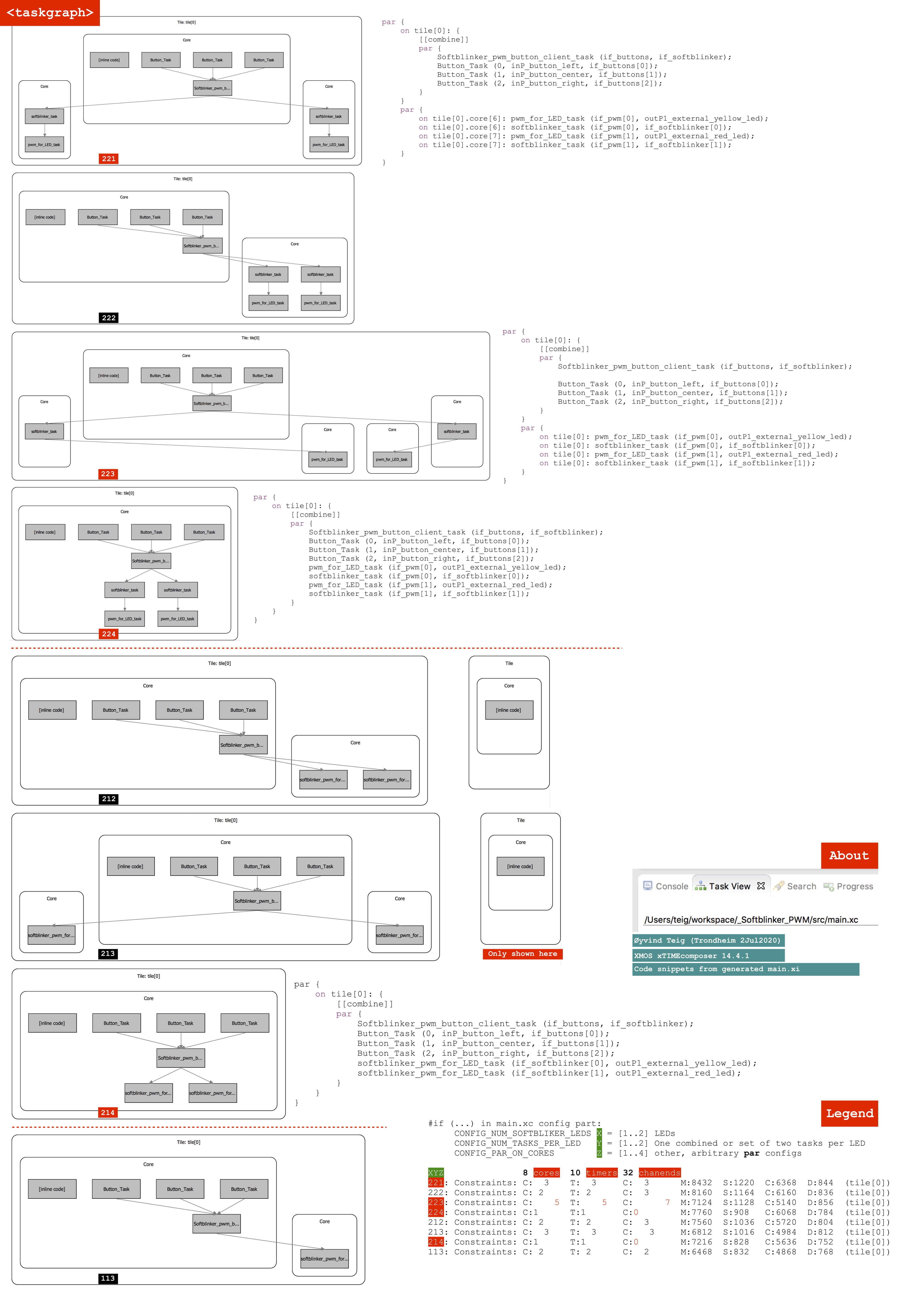
This figure shows the 8 configs I have looked further into. The first (221) is already shown. The others are three more with the two tasks for each of two LEDS (above the red, dotted line) (222, 223, 224). Then there are three configs with a merged task for each of the two LEDS, until the lower dotted line (212, 213, 214). At the bottom there is one LED and combined task (113). In the full code, alse (123) is shown. More legend in the PDF:
I figured that it was best to study this large figure off-line, therefore press the figure to see the PDF. I have shown the config code (not from the main.xc source, but from the built xTIMEcomposer .build/main.xi lower part. This is the preprocessor output, actually the one that’s compiled.
I don’t think there are many computer architectures in the world where the same code may be moved around by the system like this, depending on what I as a user, would want. The occam language had a similar configuration language, but it didn’t do the under-the-hood placement. It had less in hardware (both the transputer and the xCORE have the task scheduler in hardware. But much of the functionality has been moved by the architects David May and Ali Dixon et.al from microcode to real hardware. XMOS come after INMOS, you see.) I am a fan. (Disclaimer)
The code (2)
I showed the PWM-only code above. Here is the rest of the code. The softblinker_task and the combined softblinker_pwm_for_LED_task task.
softblinker_task
First the interface, so that we know how to talk with it from the outside:
typedef interface softblinker_if {              //  FULLY
    void set_LED_intensity_range (               // ON  OFF (opposite if port_pin_sign_e set opposite)
            const percentage_t min_percentage,  // 100   0
            const percentage_t man_percentage); // 100   0
    void set_LED_period_ms (const unsigned period_ms); // between two max or two min
} softblinker_if;
There are three interface calls. None of them return any values. No asynchronous session type defined since it’s not needed. Then the code:
[[combinable]]
void softblinker_task (
        client pwm_if         if_pwm,
        server softblinker_if if_softblinker)
{
    // --- softblinker_context_t for softblinker_pwm_for_LED_task
    timer        tmr;
    time32_t     timeout;
    bool         pwm_running;
    unsigned     pwm_one_percent_ticks;
    signed       now_percentage;
    percentage_t max_percentage;
    percentage_t min_percentage;
    signed       inc_percentage;
    // ---

    pwm_running = false;
    pwm_one_percent_ticks = SOFTBLINK_DEFAULT_PERIOD_MS * XS1_TIMER_KHZ;
    now_percentage        = SOFTBLINK_DEFAULT_MAX_PERCENTAGE; // [-1..101]
    max_percentage        = SOFTBLINK_DEFAULT_MAX_PERCENTAGE;
    min_percentage        = SOFTBLINK_DEFAULT_MIN_PERCENTAGE;
    inc_percentage        = (-1); // [-1,+1]

    tmr :> timeout;
    timeout += pwm_one_percent_ticks;

    while (1) {
        select {
            case (pwm_running) => tmr when timerafter(timeout) :> void: {
                bool min_set;
                bool max_set;

                timeout += pwm_one_percent_ticks;

                now_percentage += inc_percentage; // [0..100] but [-1..101] possible if 0 or 100 was just set in set_LED_intensity
                {now_percentage, min_set, max_set} =
                        in_range_signed_min_max_set (now_percentage, min_percentage, max_percentage); // [0..100]

                if ((min_set) or (max_set)) { // Send 100 and 0 only once
                    inc_percentage = (-inc_percentage); // Change sign for next timeout to scan in the other direction
                } else {
                    if_pwm.set_LED_intensity ((percentage_t) now_percentage); // [0..100]
                }

            } break;

            case if_softblinker.set_LED_intensity_range (const percentage_t min_percentage_, const percentage_t max_percentage_): {
                debug_print ("set_LED_intensity %u %u\n", min_percentage_, max_percentage_);

                // Conflict with jumping above or below present range resolved with in_range_signed_min_max_set in timerafter

                                                                 // Also overflow/underflow problems solved there:
                min_percentage = (percentage_t) min_percentage_; //   0 here and min_percentage may be decremented to  -1 in timerafter
                max_percentage = (percentage_t) max_percentage_; // 100 here and max_percentage may be incrmeneted to 101 in timerafter

                if (max_percentage == min_percentage) {
                    pwm_running = false;
                    if_pwm.set_LED_intensity (max_percentage);
                } else if (not pwm_running) {
                    pwm_running = true;
                    tmr :> timeout; // immediate timeout
                } else { // pwm_running already
                    // No code
                    // Don't disturb running timerafter
                }
            } break;

            case if_softblinker.set_LED_period_ms (const unsigned period_ms): {
                debug_print ("set_LED_period_ms %u\n", period_ms/MS_PER_PERCENT_TO_PERIOD_MS_FACTOR);

                pwm_one_percent_ticks = ((period_ms/MS_PER_PERCENT_TO_PERIOD_MS_FACTOR) * XS1_TIMER_KHZ);
            } break;
        }
    }
}
I will not explain this as thoroughly as the pwm_for_LED_task. But it follows the same template.
softblinker_pwm_for_LED_task
If you just about grasped the pwm_for_LED_task and the softblinker_task then this is the merged task. I wrapped the two sets of local variables in the previous tasks into softblinker_context_t and pwm_context_t so it’s easier to understand what’s happening.
With conditional compilation I make sure that either two two tasks above are mapped in, and on the cores – or this one only.
typedef struct pwm_context_t {
    timer           tmr;
    time32_t        timeout;
    port_pin_sign_e port_pin_sign;
    unsigned        pwm_one_percent_ticks;
    time32_t        port_activated_percentage;
    bool            pwm_running;
    port_is_e       port_is;
} pwm_context_t;

typedef struct softblinker_context_t {
    timer        tmr;
    time32_t     timeout;
    bool         pwm_running;
    unsigned     pwm_one_percent_ticks;
    signed       now_percentage;
    percentage_t max_percentage;
    percentage_t min_percentage;
    signed       inc_percentage;
} softblinker_context_t;
I have not changed any of the code, however the interface call if_pwm.set_LED_intensity in softblinker_task has been replaced by a function call set_LED_intensity. A task can of course not send an interface call to itself. It would have deadlocked, since it is synchronous.
void set_LED_intensity (
        pwm_context_t       &pwm_context,
        out buffered port:1 outP1,
        const percentage_t  percentage)
{
    pwm_context.port_activated_percentage = percentage;

    if (pwm_context.port_activated_percentage == 100) { // No need to involve any timerafter and get a short off blip
        pwm_context.pwm_running = false;
        ACTIVATE_PORT(pwm_context.port_pin_sign);
    } else if (pwm_context.port_activated_percentage == 0) { // No need to involve any timerafter and get a short on blink
        pwm_context.pwm_running = false;
        DEACTIVATE_PORT(pwm_context.port_pin_sign);
    } else if (not pwm_context.pwm_running) {
        pwm_context.pwm_running = true;
        pwm_context.tmr :> pwm_context.timeout; // immediate timeout
    } else { // pwm_running already
        // No code
        // Don't disturb running timerafter, just let it use the new port_activated_percentage when it gets there
    }
}
Then the final, merged task. The interface if_softblinker has already been defined, so we know how to talk with it from the outside. The conditional choice select cases now are 4:
[[combinable]]
void softblinker_pwm_for_LED_task (
        server softblinker_if if_softblinker,
        out buffered port:1   outP1)
{

    pwm_context_t         pwm_context;
    softblinker_context_t softblinker_context;

    softblinker_context.pwm_running           = false;
    softblinker_context.pwm_one_percent_ticks = SOFTBLINK_DEFAULT_PERIOD_MS * XS1_TIMER_KHZ;
    softblinker_context.now_percentage        = SOFTBLINK_DEFAULT_MAX_PERCENTAGE; // [-1..101]
    softblinker_context.max_percentage        = SOFTBLINK_DEFAULT_MAX_PERCENTAGE;
    softblinker_context.min_percentage        = SOFTBLINK_DEFAULT_MIN_PERCENTAGE;
    softblinker_context.inc_percentage        = (-1); // [-1,+1]

    pwm_context.port_pin_sign             = PWM_PORT_PIN_SIGN;
    pwm_context.pwm_one_percent_ticks     = PWM_ONE_PERCENT_TICS; // 10 uS. So 99% means 990 us activated and 10 us deactivated
    pwm_context.port_activated_percentage = 100;                  // This implies [1], [2] and [3] below
    pwm_context.pwm_running               = false;                // [1] no timerafter (doing_pwn when not 0% or not 100%)
    pwm_context.port_is                   = activated;            // [2] "LED on"
                                                                  //
    ACTIVATE_PORT(pwm_context.port_pin_sign);                     // [3]

    softblinker_context.tmr :> softblinker_context.timeout;
    softblinker_context.timeout += softblinker_context.pwm_one_percent_ticks;

    while (1) {
        // #pragma ordered // May be used if not [[combinable]] to assure priority of the PWM, if that is wanted
        select {
            case (pwm_context.pwm_running) => pwm_context.tmr when timerafter(pwm_context.timeout) :> void: {
                if (pwm_context.port_is == deactivated) {
                    ACTIVATE_PORT(pwm_context.port_pin_sign);
                    pwm_context.timeout += (pwm_context.port_activated_percentage * pwm_context.pwm_one_percent_ticks);
                    pwm_context.port_is  = activated;
                } else {
                    DEACTIVATE_PORT(pwm_context.port_pin_sign);
                    pwm_context.timeout += ((100 - pwm_context.port_activated_percentage) * pwm_context.pwm_one_percent_ticks);
                    pwm_context.port_is  = deactivated;;
                }
            } break;

            case (softblinker_context.pwm_running) => softblinker_context.tmr when timerafter(softblinker_context.timeout) :> void: {
                bool min_set;
                bool max_set;

                softblinker_context.timeout += softblinker_context.pwm_one_percent_ticks;

                softblinker_context.now_percentage += softblinker_context.inc_percentage; // [0..100] but [-1..101] possible if 0 or 100 was just set in set_LED_intensity
                {softblinker_context.now_percentage, min_set, max_set} =
                        in_range_signed_min_max_set (softblinker_context.now_percentage, softblinker_context.min_percentage, softblinker_context.max_percentage); // [0..100]

                if ((min_set) or (max_set)) { // Send 100 and 0 only once
                    softblinker_context.inc_percentage = (-softblinker_context.inc_percentage); // Change sign for next timeout to scan in the other direction
                } else {
                    set_LED_intensity (pwm_context, outP1, (percentage_t) softblinker_context.now_percentage); // [0..100]
                }

            } break;

            case if_softblinker.set_LED_intensity_range (const percentage_t min_percentage_, const percentage_t max_percentage_): {
                debug_print ("set_LED_intensity %u %u\n", min_percentage_, max_percentage_);

                // Conflict with jumping above or below present range resolved with in_range_signed_min_max_set in timerafter

                                                                                     // Also overflow/underflow problems solved there:
                softblinker_context.min_percentage = (percentage_t) min_percentage_; //   0 here and min_percentage may be decremented to  -1 in timerafter
                softblinker_context.max_percentage = (percentage_t) max_percentage_; // 100 here and max_percentage may be incrmeneted to 101 in timerafter

                if (softblinker_context.max_percentage == softblinker_context.min_percentage) {
                    softblinker_context.pwm_running = false;
                    set_LED_intensity (pwm_context, outP1, softblinker_context.max_percentage);
                    // No code, timerafter will do it
                } else if (not softblinker_context.pwm_running) {
                    softblinker_context.pwm_running = true;
                    softblinker_context.tmr :> softblinker_context.timeout; // immediate timeout
                } else { // pwm_running already
                    // No code
                    // Don't disturb running timerafter
                }
            } break;

            case if_softblinker.set_LED_period_ms (const unsigned period_ms): {
                debug_print ("set_LED_period_ms %u\n", period_ms/MS_PER_PERCENT_TO_PERIOD_MS_FACTOR);

                softblinker_context.pwm_one_percent_ticks = ((period_ms/MS_PER_PERCENT_TO_PERIOD_MS_FACTOR) * XS1_TIMER_KHZ);
            } break;
        }
    }
}
External connections
Even if the xCORE-200 explorerKIT contains two user buttons (two inputs on 4-bits port XS1_PORT_4E) and one green LED and one RGB LED (1+3 outputs, all on 4-bits port XS1_PORT_4F) I chose to solder my own. I wanted one more button and two LEDs that felt softer to look at, and I wanted them all to be connected to 1-bit ports so that I could assign them to separate tasks. In xC it is not allowed to send the same port to more than one task. So much safer than a port just being an address. I must admit, I have seen some of that. But then, xC knows what a port is (next chapter).

Fig.6 – External connections of two LEDs and three buttons (PDF)
Driver for LED strips
12V DC input supplying the two LED strips, driven by two HEXFET MOSFET transistors IRLU2905PBF. The gates are driven from 3.3V with an 82k pulldown to make them off when not connected (R4, R7). The gate series resistor of 1k (R3, R6) limits the slew rate and thus limit the RFI (Radio Frequency Interference). This works because the gate has some gate-to-source capacitance. There are pull-up resistors of 3.3k (r2, R5) so that the microampermeter (-100µA – 0 – 100µA) may also be sourced from somewhere – since I don’t have active pull-up, only pull-down. It will how the medium difference between the two LED strips. See movie (below). There also are two LEDS that would go in parallel with the two LED strips. They are powered by 5V, so that they will lit also when there is no 12V. The Schottky diodes (Z1, Z2) are there to remove interference from 12V. Schottky type, because they have a lower on voltage, and because I had them! Also, a blue LED and a beeper are shown here. They are used as feedback during some of the button pressing. (I will come back with usage of the three buttons.)
Aside: If I had needed a proper pullup as well, I could have used an H-bridge chip, consisting of two push-pull pairs of MOSFETS. These are often used for motors, to make switching of polarity possible. I would in case have bought a chip driver, like the L293D or L9110, or like the DRV8876 which also does current sensing.

Fig.11 – MOSFET drivers for hex strips (PDF)
xCORE extended port functions
This may turn out to be a large chapter, later on. My code in pwm_for_LED_task only uses the 1-bit port pin naïvely. It either outputs low or high. And it’s driven by an xC timer.
It’s not driven by a clock connected to the port pin, which is possible on the xCORE. Any port on these devices may be connected to one of the (six) clock blocks. By default all pins are connected to clock block 0. Each of the ports have a shift register and a 16-bits counter. Ports are 1, 4, 8, 16 or 32 bits wide. In xC one can wait for a pin, or make it behave like a clock signal. A port output may be directly timed and even timestamped, so that one output statement may be time-wise connected to another, disregarding how many xC code cycles were used for the xC code in between. If this xC code is a Normal task (not using [[combinable]] or [[distributable]], ie. running on a logical core by itself, see the CPA 2018 fringe note reference (above)) then the timing of the port (logical core’s ability to run the cycles) is deterministic. There is no interrupt that clutters it all, because there is no such thing as an interrupt. The deterministic system of the xCORE takes care of this functionality. XMOS has said that the xCORE architecture is between ASIC and standard microprocessors. It certainly is. Each port also has a buffer of one position. Ports may also be synchronised to each other.
My PWM is rather nice, I think. But it would have an upper MHz limit. I assume that by building a PWM using more of the port infrastructure might make it spin faster. But then, faster than almost as fast as possible? Well, it might at least serve as an example of port usage.
I will query about this at the xCore Exchange forum.
Timing analysis
The xCC compiler is able to validate timing requirements during compilation. Not is my first time to test this out. I found 141:[21] (XMOS Timing Analyzer Manual) and just below 141:[22] (AN00192: Getting Started with Timing Analysis in xTIMEcomposer Studio) to help me start. It wasn’t too hard to get going.
I wanted to find the guaranteed max loop time of the select in pwm_for_LED_task. I followed the recipes and set start point and stop point at line 1 and 6 (my names). I compiled as config (225) (above)). The tool inserted two #pragma for me. Nice, since they can’t be on any line. The tool showed which ones. I think it’s basically on I/O lines.
    while (1) {
        #pragma xta endpoint "start"
        select {
            case (pwm_running) => tmr when timerafter(timeout) :> void: {
                if (port_is == deactivated) {
                    #pragma xta endpoint "stop"
                    ACTIVATE_PORT(port_pin_sign);
                    timeout += (port_activated_percentage * pwm_one_percent_ticks);
                    port_is  = activated;
                } else {
                    DEACTIVATE_PORT(port_pin_sign);
                    timeout += ((100 - port_activated_percentage) * pwm_one_percent_ticks);
                    port_is  = deactivated;;
                }
            } break;
First I had it analyze the timing from start to stop, but it gave little meaning. So I had it export to an xta script file: my_script.xta. 1.0 µs required for the loop time should be ok, just for a start. My PWM_ONE_PERCENT_TICS is 100 µs, a light year away.
analyze loop start
set required - 1.0 us
(For other cases alternatives would be analyze function x, analyze endpoints a b). (Also observe that if xta tells that «error: ‘start’ is not a valid loop point on any active tile» it probably only means that start is also defined in another file). I compiled with configuration (223). This was rather essential, it has to know how the code runs. I don’t know the details about that yet. So very nice to see the result presented. I just love this:
..
xta: .././2020_07_03_B_script.xta:7: warning: route(0)     Pass with 14 unknowns, Num Paths: 12, Slack: 760.0 ns, Required: 1.0 us, Worst: 240.0 ns, Min Core Frequency: 120 MHz
..
I can also xscope the timing inside xTIMEcomposer if I use the simulator. I haven’t tried that on this example yet.
Two movies
Fig.8 – Microamperemeter (µA) instrument showing two PWMs differential voltages
The above, first movie, shows how my two LED strips will show up when I do two softblinking sequences out of phase. There is no sound. The «vibration» of the light that you may notice, is interference between the camera shutter and the PWM on/off. However, on the table the LED strips look smooth to the eye. The movie also has a glimpse of the XMOS eXplorerKIT.
The oscilloscope screen and the microamperemeter are also seen. Observe in the diagram (fig.11), there is no capacitor to smooth the signal. That’s not necessary with an analogue instrument, where the mass and the spring will take care of averaging.
 Update: That µA instrument was not easy to get hold of. What are they called? Horisontal? Some time after I found some at eBay I discovered this ad (picture, small part of a 3-page ad) in a Wireless World magazine from Sept. 1972, from G.W.Smith & Co (Radio) Ltd in London. I was 22 in 1972, and have kept some old magazines of the sort. This type of instrument seems to be called an edgwise meter. I updated at Wikipedia, here.
The movie also shows my home made plastic box, made from sheet (..I think..) plexiglass, SAN plastic and a piece of 90° bent polycarbonate (Lexan) from a nearby shop. (Found when I walked behind the shop. Bending this I just cannot do myself. I have tried.) (Some more about plastic at My materials science notes.)
Fig.10 – School physics demonstration soft iron instrument showing two PWMs differential voltages

Fig.9 – School physics soft iron instrument
The above, second movie, shows a situation where I have added the beauty of a school physics demonstration voltmeter (of soft iron type). Also this movie does not have sound.
My neighbour showed me a box of some physics course stuff that had been laying around for quite some years at her school (Bispehaugen skole here in Trondheim), which they were going to get rid of.
When I saw that voltmeter I got the idea to borrow it and place it across my two LED strips. This predates the microamperemeter final solution, shown in the first movie. (Thanks, neighbour Marit!)
However, since I only have pulldown transistors I had to make a pullup resistor from each MOSFETs transistor’s output, to the 12V power. (Overview in Fig.11, but those details are not there.) (As mentioned earlier, I did not design an H-bridge.) Both resistors are 17.6 Ohm, made from some five resistors in all (12Ω||12Ω + 12Ω||12Ω + 5.6Ω). (|| means «in parallel» and + «in series»). In sum this would be a maximum power of 12V / 17.6Ω = 0.68A → 12V * 0.68A = 8.2 Watt. This will happen during the situation of full difference: with one LED strip fully on and the other fully off. The mean power of the resistors would certainly be less. But they go quite hot. So it’s only for demoing.
A fun thing is that the coil will sound with the 222 Hz plus interesting harmonics – it’s weak, but audible. (But it didn’t come across to the movie, adding no need to not remove the bacground sound.) The springs and mass of the instrument make it not as much damped as in the microamperemeter; there is some resonance phenomenon visible. You can also see that the microamperemeter now gets much less range (as compared to the first movie) since the low impedance old school beauty and its resistors eat their lot. (With this language the paragraph certainly shows that I haven’t calculated on this circuit..)
Some more asides
Arm LDEX/STEX
Concering the possible deterministic behaviour of xC and the XMOS cores. I discovered that in the Arm world there is something like a «Time-deterministic interrupt execution: RTX5 utilizes the LDEX/STEX instruction available on most Cortex-M processors and therefore user interrupts are never disabled.» (here). I found that quote following links in an Arm blog note about the Cortex-R5. LDEX/STEX loads and stores atomically to a cell marked as exclusive by the load, meaning that the exclusive store STEX may fail (here). That’s nondeterministic in my head. Maybe I’ll add this to my Nondeterminism note one day.
Looking through a fidget spinner

(New 26Feb2022). A fidget spinner is an excellent instrument to detect if something is blinking faster than you are able to see with the eye. The stroboscopic effect lets only parts of a timed sequence through its holes, making a still or left/right-rotating pattern with different speeds show up. If those parts match exacly with the visisble/hide pattern then the view looks still. (See Wiki-refs below).
I did try to make a movie, but the shutters of the mobile or my hand held camera showed up just as much as the stroboscopic effect.
My PWM LEDs will show no such effect at 100% LED on, since there is not a microsec of «off time» in that case. But as soon as I dim it down, the stroboscopic effect shows up.
That being said, a mobile camera on slow mode is also an ok tool if you don’t have a fidget spinner at hand. Try a shot of anything you suspect is pulse modulated and have a look.
There is an excellent YouTube presentation «Shining a Strobe Light on a Spinning Fidget Spinner and Projector Light Separation» by The Action Lab (here). It doesn’t show my example, but it’s close.
Summary
This became a rather code centric note. I have shown a function that softblinks a single LED that is instantiated as two tasks when two LEDS need to softblink independently. I have shown that a LED may get a new on/off-ratio value, typically (linearly) every 30 ms, so that it softblinks from zero to max, in percentage steps, in 3 seconds.
I have not shown the SW external to this (but the full code may be downloaded), except fragments from main.xc, where the task structure is configured in different ways. What follows from this has also been shown, although rather superficially.
It has also been interesting to see how two easy to read tasks have been merged into one not so easy to read single task. The tool’s configuration has helped us understand that in some cases using this merged task is not optimal. But sometimes it is optimal, though. Especially since the tool, in some cases, builds a merged task (from [[combinable]] tasks) under the hood. The simplicity of two tasks with some communication between them (coupling) is valued against the increased inner complexity (cohesion) of the combined task.
Not dimming in general
The purpose of this note was to show some idiomatic «pure task-type» pulse width modulated (PWM) dimming – for anything that is dimmable that way. Like LEDs. But dimming in general is not covered.
I remember that I used to build 230V AC dimming boxes when I was young, implemented with a TRIAC, a potmeter and an RC network, to control the phase for the controlling gate. This was for incandescent light bulbs, something we used to use for lighting. Not so young I learning how the company I worked for, Autronica, before my time, had used transductors to control the lighting of the largest cinema in Norway (Colosseum kino in Oslo, after the fire in 1963). I haven’t studied how modern, dimmable LED lamps are dimmed. But I just assume that there is some kind of PWM in charge. For sure, my variac (variable transformer, a type of autotransformer) is not of much use. Maybe this could be a follow-up from this note?
User forums
xCore Exchange forum
- Synchronising multiple threads started by leobodnar on 15Oct2020 and responded to by me, with a reference to here on 29Oct2020. I show the
barrier_do_chan_taskbarrier task there
The looks of code. The understanding
Lastly an aside:
        ,,,
       (o o)
---oOO--(_)--OOo---
I started this with line editors. A full screen of code could be seen (listed) only on the 80 char wide screen. Before I left the teletype I had to save to punched paper tape. After some years I discovered that the screens had gotten wider. And do I miss a real folding editor?
:
Yes: Wishes for a folding editor. With it I could bring any number of lines into a single screen. Hide any number of indents away from scope. With three arrows down and passing of a fold the line number could go from 42 to 273. And a fold was a native citizen of the editor. Not just hiding as the Eclipse does on the xTIMEcomposer. It’s nice, but not near winf32 that I used on Windows until I retired. But at my home office I have macOS (with Windows and Parallels Desktop, but winf32 became too awkward across the operating systems. But I haven’t given up on it, have I..) And yes, I have read my Code Complete by Steve McConnell.
27Aug2021, version 0.7.3 of _Softblinker_PWM and 0.8.3 og lib_pwm_softblinker.
I have seen grandchild Jakob (10) being attracted to this box and lamp. He has learned some of the rather awkward buttons scheme. But then I though that at power up, maybe it wasn’t so smart to let it have a period of 10 secs from 0 to max, forever. Any user, I guess, would be most interested in just a steady lit lamp with a dimming control. And should the lamp be on when one goes on a holiday and the mains decide to do dip, then a restart of the old sort would cause much attraction to anyone – on the street.
I decided to let the unit simulate 8 button presses as a start-up sequence. With depressed and released it would simulate 16 button actions. First the initial complete 10 secs soft down and up, then a change of mode to state_all_LEDs_stable_intensity and then 7 presses from 100% down to 30% light. The movie (below) does not show the nuances of the LED tower’s light level, very well, since the camera is rather saturated with the levels. But the scope and the beeper make sense:
Fig.16 – Simulations at power-up. The controller unit is the right, topmost box
I guess the most interesting code parts now would be:
// SIMULATE BUTTONS AT POWER UP
//
#define DO_BUTTONS_POWER_UP_SIMULATE_ACTIONS 1
//
#define NUM_BUTTONS_POWER_UP_SIMULATE_ACTIONS 16
//
const int iof_buttons [NUM_BUTTONS_POWER_UP_SIMULATE_ACTIONS] =
{
                                          // state_red_LED_default
    IOF_BUTTON_CENTER, IOF_BUTTON_CENTER, // state_all_LEDs_stable_intensity
    IOF_BUTTON_LEFT,   IOF_BUTTON_LEFT,
    IOF_BUTTON_LEFT,   IOF_BUTTON_LEFT,
    IOF_BUTTON_LEFT,   IOF_BUTTON_LEFT,
    IOF_BUTTON_LEFT,   IOF_BUTTON_LEFT,
    IOF_BUTTON_LEFT,   IOF_BUTTON_LEFT,
    IOF_BUTTON_LEFT,   IOF_BUTTON_LEFT,
    IOF_BUTTON_LEFT,   IOF_BUTTON_LEFT
};
//
const button_action_t button_actions [NUM_BUTTONS_POWER_UP_SIMULATE_ACTIONS] =
{
                                                          // state_red_LED_default
    BUTTON_ACTION_PRESSED, BUTTON_ACTION_PRESSED_FOR_LONG,// state_all_LEDs_stable_intensity
    BUTTON_ACTION_PRESSED, BUTTON_ACTION_RELEASED,        // 90% light
    BUTTON_ACTION_PRESSED, BUTTON_ACTION_RELEASED,        // 80% light
    BUTTON_ACTION_PRESSED, BUTTON_ACTION_RELEASED,        // 70% light
    BUTTON_ACTION_PRESSED, BUTTON_ACTION_RELEASED,        // 60% light
    BUTTON_ACTION_PRESSED, BUTTON_ACTION_RELEASED,        // 50% light
    BUTTON_ACTION_PRESSED, BUTTON_ACTION_RELEASED,        // 40% light
    BUTTON_ACTION_PRESSED, BUTTON_ACTION_RELEASED         // 30% light
};
//
#define BUTTONS_POWER_UP_SIMULATE_MS 100
//
const pre_button_action_delay_ms [NUM_BUTTONS_POWER_UP_SIMULATE_ACTIONS] =
{
    DEFAULT_SOFTBLINK_PERIOD_MS, // 10 secs. Observe one period
    BUTTONS_POWER_UP_SIMULATE_MS, DEFAULT_SOFTBLINK_PERIOD_MS/10,
    BUTTONS_POWER_UP_SIMULATE_MS, DEFAULT_SOFTBLINK_PERIOD_MS/10,
    BUTTONS_POWER_UP_SIMULATE_MS, DEFAULT_SOFTBLINK_PERIOD_MS/10,
    BUTTONS_POWER_UP_SIMULATE_MS, DEFAULT_SOFTBLINK_PERIOD_MS/10,
    BUTTONS_POWER_UP_SIMULATE_MS, DEFAULT_SOFTBLINK_PERIOD_MS/10,
    BUTTONS_POWER_UP_SIMULATE_MS, DEFAULT_SOFTBLINK_PERIOD_MS/10,
    BUTTONS_POWER_UP_SIMULATE_MS, DEFAULT_SOFTBLINK_PERIOD_MS/10,
    BUTTONS_POWER_UP_SIMULATE_MS
};

[[combinable]]
void softblinker_user_interface_task (
        server button_if      i_buttons_in[BUTTONS_NUM_CLIENTS],
        client softblinker_if if_softblinker[CONFIG_NUM_SOFTBLIKER_LEDS],
        out buffered port:1   outP_beeper_high)
{
    beep (outP_beeper_high, 0, 250);

    timer        tmr;
    time32_t     time_ticks; // Ticks to 100 in 1 us
    ui_context_t ctx; // PWM=011
    int          iof_buttons_power_up_simulate;

    #if (DO_BUTTONS_POWER_UP_SIMULATE_ACTIONS == 1)
        #if (WARNINGS==1)
            #warning Button simulation at power up
        #endif
        iof_buttons_power_up_simulate = 0;
    #else
        #if (WARNINGS==1)
            #warning No button simulation at power up
        #endif
        iof_buttons_power_up_simulate = NUM_BUTTONS_POWER_UP_SIMULATE_ACTIONS; // skip them
    #endif

    debug_print ("softblinker_user_interface_task sim_cnt=%u\n", iof_buttons_power_up_simulate);

    // INIT
    ctx.LED_phase                          = IN_PHASE;
    ctx.a_side_button_pressed_while_center = false;
    for (unsigned ix = 0; ix < BUTTONS_NUM_CLIENTS; ix++) {
        ctx.buttons_action[ix] = BUTTON_ACTION_VOID;
    }
    // INIT those that were const in 0066 (const'ness lost with ui_context_t)
    {
        const unsigned period_ms_list [PERIOD_MS_LIST_LEN] = PERIOD_MS_LIST;
        for (signed ix=0; ix < PERIOD_MS_LIST_LEN; ix++) {
            ctx.period_ms_list[ix] = period_ms_list[ix]; // const
        }
        const intensity_steps_e intensity_steps_list_short [NUM_INTENSITY_STEPS_SHORT] = INTENSITY_STEPS_LIST_SHORT;
        for (signed ix=0; ix < NUM_INTENSITY_STEPS_SHORT; ix++) {
            ctx.intensity_steps_list_short [ix] = intensity_steps_list_short[ix]; // const
        }
    }

    set_params_to_default (ctx.params);

    write_to_pwm_softblinker (if_softblinker, ctx.params);

    set_states_LED_views_to_default (ctx.params, ctx.states_LED_views, ctx.synch_all);

    tmr :> time_ticks;
    time_ticks += (XS1_TIMER_KHZ * pre_button_action_delay_ms[iof_buttons_power_up_simulate]);

    while (true) {
        select { // Each case passively waits on an event:

            // BUTTON ACTION (REPEAT: BUTTON HELD FOR SOME TIME) AT TIMEOUT
            //
            case (iof_buttons_power_up_simulate < NUM_BUTTONS_POWER_UP_SIMULATE_ACTIONS) => tmr when timerafter (time_ticks) :> void : {

                handle_button (
                        iof_buttons   [iof_buttons_power_up_simulate],
                        button_actions[iof_buttons_power_up_simulate],
                        ctx,
                        if_softblinker,
                        outP_beeper_high);

                iof_buttons_power_up_simulate++;
                if (iof_buttons_power_up_simulate < NUM_BUTTONS_POWER_UP_SIMULATE_ACTIONS) {
                    time_ticks += (XS1_TIMER_KHZ * pre_button_action_delay_ms[iof_buttons_power_up_simulate]);
                } else {}

            } break; // timerafter

            // BUTTON PRESSES
            //
            case i_buttons_in[int iof_button].button (const button_action_t button_action) : {

                if (iof_buttons_power_up_simulate == NUM_BUTTONS_POWER_UP_SIMULATE_ACTIONS){
                    handle_button (
                            iof_button,
                            button_action,
                            ctx,
                            if_softblinker,
                            outP_beeper_high);
                } else {}

            } break;
        }
    }
}
Observe that the code download (below) has a slightly different version to the one described here. In that version the left LED, for the first ten seconds, would do two periods instead of one, making the left and right LED towers to be out of phase. It’s nicer, also since the µA-meter then takes part in the start-up sequence. Plus, I take the intensity all the way down to 10%.
I did find an error while I did this, an error that has been there all the time. In the PWM task itself (in lib_pwm_softblinker) I had switched off the PWM when the lights were either 0% or 100%. However, there was a case when I hadn’t set the timeout select case guard to true again, causing a dark LED tower for exactly time32_t half = 21.47483648 secs – which indicated that an «after» had wrapped over. Search for PWM=012 in the download to see. (It’s actually in this url, also shown in the «direct read» file #1 below: https://www.teigfam.net/oyvind/blog_notes/209/src_txt/pwm_softblinker.xc.txt.)
The fix caused the xta tool to see a failed deadline of 1.0 µs. I had to increase it to 1.1 µs. This value was just for the testing, it’s not bound to any spec (search for PWM_ONE_PERCENT_TICS).
This is all done after I temporarily put XTC Tools (which does not even support the xta tool) on hold and went back to xTIMEcomposer 14.4.1 (222:[14.4.1 on a reserved machine!].
The code (download)
For the code shown here
It contains the XMOS xTIMEcomposer project _Softblinker_PWM. No password. It also contains the full history with the git versioning. The system is built with XMOS xTIMEcomposer (14.4.1).
The source files listed:
_Softblinker_PWM.h
_Softblinker_PWM.xc
_globals.h
_texts_and_constants.h
_version.h
button_press.h
button_press.xc
main.xc
maths.h
maths.xc
pwm_softblinker.h
pwm_softblinker.xc
For xC code that really does something with the buttons (and a display), I have some here: My processor-to-analogue audio equaliser notes @ The code (download).
For newer and updated code
This is the code that’s updated. Download from My xC code downloads page #209.alive.
Plus, here are two «direct read» txt files:
- https://www.teigfam.net/oyvind/blog_notes/209/src_txt/pwm_softblinker.xc.txt – from lib_pwm_softblinker
- https://www.teigfam.net/oyvind/blog_notes/209/src_txt/_notes.txt – the buttons «manual». Also read as PDF at LED tower and control box
This code also contains a barrier code, barrier_do_chan_task. I discussed this at xCore Exchange forum (first point). David May also discusses barrier synchronisation and how that’s used in the xCore architecture in 141:[24]. 141:[24], 141:[25], 141:[26], 141:[27]
References
Wiki-refs: Class-D amplifier. Fidget spinner. H-bridge. Pulse-width modulation: Soft-blinking LED indicator. Stroboscopic effect. Switched-mode power supply. Transductor. TRIAC
Much referencing in the About xC chapter above.
 Make: Electronics. Second ed. By Charles Platt at Maker Media. Tenth release, 7Sep2018, ISBN 978-1-680-45026-2. See https://www.makershed.com/products/make-electronics-2ed