
Contents
Purchase and parts list
- Aside 1: I also sold my PicoScope (Sep2019)
- Aside 2: Used for sale: USB scopes. Sold
This was bought from direcly from BitsScope in Australia in May2015. It basically costs the same in USD today (Sep2019) ($245 for BS10U).
CODE  PRODUCT               USD     AUD   NOK
SP01A BNC PORT ADAPTER      $32.45
CLP02 EXTRA TEST CLIPS      $39.45
DP01A DUAL CHANNEL ACTIVE
      DIFFERENTIAL PROBE(*) $75.45
BS10U USB BITSCOPE 10      $245.00
PRB01 TWO 10:1 ANALOG
      PROBES @$34.95        $69.90
                 DELIVERY   $31.93
                      SUM  $498.18  644  3931
MOMS OG AVGIFTER FRA FedEx                886
                                     SUM 4817
(*) Out of stock Sep2019.
Plus POM-plastic cramps that I made for the scope box and the BNC port adapter.

Fig.0 – All parts Sep2019 (press for more pixels)
Present feeling
I also added a PicoScope to my desk (Sep2017). See below, here. And after that (Jan2019) I bought a SIGLENT desktop scope, see My SIGLENT scope log
Intro
The precursor to this note was my need for an oscilloscope as disclosed while I was writing the My XMOS notes, and my limited research comparing two scopes in the A scope to fulfill note. I ended up here. You may read some initial matters on the BitScope BS10 in the latter note. This note should then be whatever comes my way when I start using:
- BitScope BS10 scope unit plus
- bitscope-dso.app 2.6 (as dmg file)
- UFTDIUSBSerialDriver_v2_3 USB serial driver (as dmg file)
I have also downloaded these:
- bitscope-chart.app 1.1 (as tar file)
- bitscope-logic.app 1.2 (as tar file)
- bitscope-meter.app 2.0 (as tar file)
Disclaimer 1: I have no association with BitScope and there is no money involved neither with this nor any other blog notes of mine. (Well, that’s not completely true: I have happily bought a BS10 etc. from Australia!) Here I will blog about my experience with this, and see what is and what might be in it for me. Disclaimer 2: I am no oscilloscope specialist!
My inventory
On 7May2015 I purchased this from BitScope’s shop: BS10U USB BITSCOPE 10 $245.00, DP01A DUAL CHANNEL ACTIVE DIFFERENTIAL PROBE $75.4, SP01A BNC PORT ADAPTER $32.45, CLP-02 EXTRA TEST CLIPS $39.45, PRB-01 10:1 ANALOG PROBE (2) $69.90, SUM USD $494.18 (NOK 3930) (including $31.93 postage half way around the world. Friday from Australia, Tuesday afternoon at my door!) Norwgian customs etc. (invoice from FedEx) was NOK 862 ($112). Sum about NOK 4800. This is not expensive for an oscilloscope, but it’s absolutely on some limit of what I’m willing to spend at home.
My little lab bench

First is #01.01
- When I first tried the BitScope BS10 on my XMOS startKIT set-up (which now has temperature, buttons and a I2C display connected) I saw that it was easy to have the scope cables slip off since the pieces were so light and then easy to push around by accident. So I let my present vitrine wall cabinet work leave over for a day and threw myself into making a little lab bench. I took some plastic cutting boards (yes, I keep some of them in my shop for material) and built a two-floor construction (ground floor for cables, USB hub, power etc.). I also had some solid plastic (some waste from an in-building company, once used for a mold for some silicon cast; nice to have) that I made hold the two floors together and most importantly, for a frame for the tiny BS10. All pieces were screwed together.
- After the pictures were taken I have bored small fastening holes for whatever need. Cutting boards are easy to bore through, and holes may be reused later on.
- The BS10 can be moved back and forth inside the frame. I made a front for the BitScope HammerHead BNC connector. It’s pushed so tightly down into the top floor that it sits firmly. It will save the scope probes from lifting the BS10 into the air and perhaps break something. When the BS10 is pushed ahead it connects straight into the back of the now fastened HammerHead adaptor. Now I can carry my complete lab bench around! Or better: keep all the pieces together in one place.
BitScope DSO client’s user interface
First is #02.01
- (DSO 2.6) I fully accept that when you are new to a user interface not everything can or shall be intuitive. Something has to be learned. My first lesson will be to learn how to see the difference between state (what are the settings now?) and function (options for change and how to?). There is a learning curve here, that’s for sure. I notice on 2.9 FE22C that a maximised window leaves a space of a pixel or two above the window before the OS X top line.
- (DSO 2.6) The OS X version’s Maximise button doesn’t do 100% full screen (see figure at #06.01, below). The Dock plus the top menu line are left. I think Apple changed some semantics with 10.10 Yosemite. A change may not be possible since the client runs on several platforms. But the xTIMEcomposer (again, note 098) in Java on Eclipse did manage the change (no visible OS X stuff left, only application. Even if the Dock else doesn’t hide automatically).
- (DSO 2.6) It starts with a rotating ellipse with the company name on. Is this a relic of some earlier version? It’s mathematics, so it’s nice of course – but what’s in it for me? It reminds me of an early Windows screen saver.
- I can unplug the scope and as much as I want put the machine in sleep mode, but when plug in the BS10 again all is working erfectly. The client hooks anto the BS10 very well. I have seen no hickups. I don’t even have to see the screen because the LEDs on the BS10 tell me that it’s still trigging. (That being said: I also have seen it get lost with no data from BS10, where unplugging it and inserting it again helped)
- I like the fact that new curves are bright but then they go darker. It reflects the dynamic aspect of a scope.
- (DSO 2.6) Frame rate goes from F/Sec down to 100 mF/Sec. Why not inverse the scale for those needing more than a second per frame and instead, like for the slowest call it 10 Sec/F?
- DSO 2.9 beta developer edition (build FE22C) appeared in a mail 26May2015 (here). But that was for Windows, Raspberry Pi and Linuxs only. The Mac OS X version appeared after some days. In the wait BitScope did respond on the support board. They told in the 2.9 beta release mail that there had been a bug in the Mac build server, and that all platform releases are indeed supposed to appear at the same time. Good for us Mac users; we should expect to be en par with the other platforms. Update 12July2015: version 2.9 beta (build FE22G) for «Machintosh» (sic, it’s Macintosh) did arrive with the other platforms («Windows (all), Machintosh (all), Raspberry Pi, Debian Linux 32 bit, Fedora Linux 32 bit, Debian Linux 64 bit, Fedora Linux 64 bit»)
Roll (streaming) mode
I’d like to have this on the BitScope. In a support may they say I should watch this card. It uses PiLab, their open platform written in Python for the BitScope Virtual Machine. Python has become popular also for this kind of work. By the way, here’s an exciting library for multithreading in Python: PyCSP. Here’s is what I mean:
The curves below are measured on old matter that Autronica obsoleted in new products some years ago, published in the early eighties. It may be measured on site on any Autronica fire detection loop’s detector. There are millions out there, so this is no secret! Autronica had the first addressable fire detection loop, already in the late seventies. The panel was with discrete logic only, but the subsequent BS-30 and BS-100 had several processors each (also called BS30 and BS100, around 1984 and 1990).

First is #03.01
- If you follow the green curve the voltage pulse train repeats about every 7 seconds. (The yellow, blue and red curves are not relevant here. I have added the yellow text.) There are 99 detectors answering with current (not seen since I haven’t connected a current probe) for some time (normal 60-70 ms). It starts with a reset pulse of 2 ms (and a wait), and then there are 99 counting pulses (each issued when the answer time has finished) of 0.5 ms each, plus one at the end. Number 22 answers with a longer time, because it’s in alarm. We can see them all while the curves horisontally scroll, roll or stream across the screen, covering the last 8 seconds. It’s easly to see what’s going on. No lost pulses because of effects in the scope. Presently the BitScope curve loses some pulses here, and it doesn’t roll. In the picture above I have made a panel of each increasing resolution’s screen save, after I stopped the curve.
- {Aside 1: When I first saw this type of curve on a scope, around 1988, it was on an analogue storage scope where the small pulses showed on the CRT and were stored there (probably it was this kind of CRT on a Tektronix scope). Usually the curve faded out fast. {Aside 2: Thinking it over I did my Master’s theses at NTH in 1975 analysing sampled heart blood pressure data {Aside 3: from a speeded-up vascocardiolar analogue simulator called «Jenny», by Rune Aaslid), read it into a Mycro-I machine (nobody had yet dreamt up the idea that it was personal) and doing synch and displaying a heart beat on a scope. The higher frame rate playback was through hardware I designed, to a Tektronix 549 storage (yes) scope with a four-channel 1A4 plug-in amplifier. For some reason I have kept the paper tape used for the 8080 cross assembler running on the Nord-1 machine. I must admit I had to look up the details!-} But the scope at work in 1988 also was a digital sampling scope, and I think it had some hardware that «sampled between the samples» so that we could see almost any short pulse, almost disregarding the sampling rate. (Take this with a grain of salt, I’ll check this up with one who probably remembers). We explicitly bought this scope to get this view; it was that important}
- It might be that just sampling fast enough is sufficient for the data aquisition. However I think that showing this on an n-pixel wide screen needs just that sampling between the samples. Like showing a 1/10 of a pixel wide pulse, if it’s gone in pixel division then rewrite it. These days it’s probably what bitmapped down-scaling do, where some of the algorithms don’t seem to lose lines. For the 900 pixel picture above I used Graphic Converter (OS X) and the Lanczos 3 algorithm that I thought was; better but checking it out maybe it wasn’t. The orignal saved pictures from the scope were 800 pixels wide, so that’s probably the resolution of that very expensive scope. So it’s not about number of pixels but about the brains before them. Press on the picture to see more pixels.
- As with any such scope, what’s possible would depend matters like:
- Sampling rate
- Available commands in the BS10 box
- Local buffering in BS10
- USB speed (it’s USB 2, not 3)
- I assume that the client sw would be able to do anything in this context; this doesn’t limit it?
- I don’t know if they can update the SW in BS10, or if the VM there with its command set is enough?
I will certainly follow the above BitScope url on this matter.
The box BS10
First is #05.01
- I haven’t read the data sheet, but it doesn’t get hot at all. So there’s no problem with the belt I made.
- The «USB 2» connector on it probably is USB Mini-B (not Micro-USB type B), but see https://trello.com/c/8YZK9OfJ
Crashes
First is #05.01
- BitScope Meter 2.0 crashed when I tried to close it after the USB had been unplugged. Mac OSX 10.10. Report automatically sent to Apple: «Hang». DSO, Chart and Logic closed fine.
- BitScope DSO 2.6 (and 2.9 FE22C). «Access violation. Press OK to ignore and risk data corruption. Press Cancel to kill the program.» I selected 20 MHz (or, it seems anything) in the WAVEFORM lower right drop-down box. It’s repeatable. Some times I the star at 20 MHz in th edrop-down list when it shows 2.5MHz on the button. This may be because it always samples as fast as possible..
Just using it
adafruit display and I2C with XMOS startKIT
First is #06.01
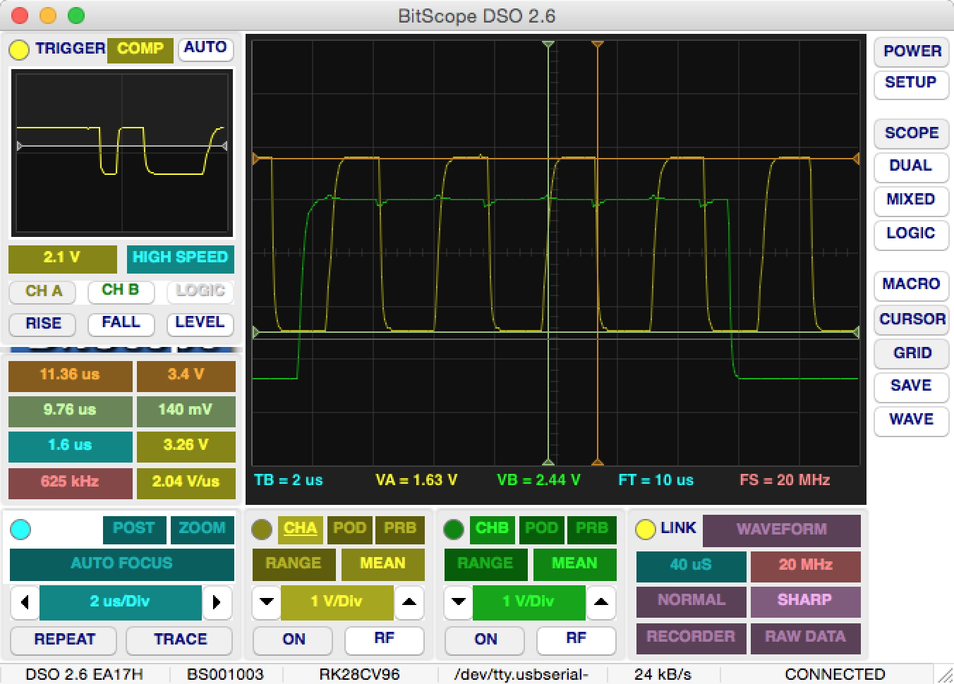
- (DSO 2.9 FE22C) The screen clip below shows the SDA and SCL lines from XMOS startKIT to the adafruit monochrome 128×32 I2C OLED display (containing a UG-2832HSWEG02 from Univision Technology Inc). I certainly fiddled around for this and had a support case with adafruit (Adafruit 931 Power: see http://forums.adafruit.com/viewtopic.php?f=8&t=75721) I also downloaded several other screen clips to that case (here), plus an iCircuit diagram. What came out of this was that the adafruit display’s Vin takes 5V or 3.3V power, depending on SDL/SLC logic level in and that the 3.3V never takes input but is a voltage regulator output for aux usage. So it typically is not connected. I did not discover this from the data sheet. (I missed the forest for the trees. For some reason I thought the display’s 3.3V pin should get 3.3V power when 3.3V logic was used, and Vin should not be connected – and Vin should have 5V and 3.3V nothing when 5V logic was used. This was wrong! This reminded me of when I was 9 and insisted that since «miniature» model trains were made of metal, then miniature meant metal – until the older and wiser, late neighbour boy Helge Skaaden, told me otherwise. But I learnt the lesson that it’s easy to see and understand as correct something that isn’t. It adds up, on wrong assumptions. See Russel’s Paradox.) But then, even if adafruit do have very good docs and tutorials the data sheet could have been more explicit about pin usage. This is about the same situation as measured in note 099 with a professional scope. The XMOS has 3.3V logic on its port pins. It works like a dream, but..

- ..here I have added 1.2K pullups to 3.3V. The display’s internal 5K (two 10K) pullups are not enough to get a decent digital signal, as I see it. As you can see, the CURSOR panel now also shows some values. It’s the XMOS i2c_module_master library that drives the pulses here. The xC language and the processors have fully equipped pin ports, with timers and shift registers. The language supports all this. And timing requirements may be set and guaranteed by the tool.

- (DSO 2.9 FE22C). Here’ s a raw SAVE from the DSO. As you see, I have use of the scope now! The SAVE is of width 1006 pixels, and that seems to be it. It’s basically the same as a screen clip (but then that’s not really defined, it depends on the size of the screen and the window, of course). Only choice of different bitmaps, no PDF or XML export with settings etc. In a future version, where we might name the cursors, this would have been quite nice. The JPG was by far not as good as the PNG, so the JPG parameter settings they use seem strange. Press the picture to go to its WordPress «attachment page» to see it unscaled in the browser. I’d say the SAVE is rather primitive, but much better than nothing.

And here’s the same graphics paste into Apple Pages together with a screen clip from the SSD1306 display controller’s data sheet. We see I2C, and we see that the controller ACKs but then there is a short pulse after it before the writer takes over the SDA line. It was easy to slide along the samples and position like this in the DSO. Push to see higher resolution:


Dual Channel Active Differential Probe
First is #11.01
- The DP01 unit is naked. I can see that it picks up EMI noise, like if I hold it close to my USB fluorescent lamp’s electronics. When I connect the balanced, twisted cable it seems like that noise goes. An unconnected input always is an antenna, but here.. are there more (that I have to take height for?)
- …
Errata
First is #07.01
- (20May2015) BitScope DSO Manual. DSP Capture Control. Typo: «No signal processing appled»
- Same place. What does it mean?: «BitScope usually captures at sample samples rates much higher the display’s sample rate.»
Errors
First is #08.01
- BitScope DSO 2.9 FE22C does not update the CONNECTED STATUS if I pull out the USB cable while I try to get a curve up. The DSO might not talk with the box and I may not be aware of it, but still. I only got an update if I push the POWER button twice.
- …
Issues that caused me to also invest in a PicoScope
After a couple of years on and off usage of my BitScope I have ended up with some issues that caused me to invest in a PicoScope:
- My test bench outgrew the scope. Analogue sampling rate of 20 MS/S is too little when I want to view a 12.5 MHz signal. No surprise, technically – but a surprise that I so fast ran into this need. Like the one we’re discussing in Loading SPI_CLK is no good (started from here). I didn’t in this case want to write a driver to loop the signal, so that BitScope’s subsampling could be used
- The bitscope-dso client I never got aquantained with. I had to try and err every time I used it. And it’s not easy to see the state of the scope, even if it is possible. It is too little like a standard oscilloscope screen. It’s some idea by a bright guy, compact but in need of much polishing to make it understandable and intuitive
- And it’s not updated! I have used 2.9 for some two years, but even now (29Sept2017) it’s 2.8 (yes, one less) that’s available as the most recent for download. Version 2.9 is some beta that was available for developers
- However, it’ still a nice instrument to use, being what it is! Like audio and things
- Next phase for me now is seen here: My PicoScope notes