Contents
Started 24Oct2022. Updated 01Sep2023. This note is in group Tech notes and sub-group E-FUN (Electronics fun). Observe that «powerbank» is written «power bank» in English here.
Disclaimer
The ultimate standard of how a USB power source communicates with a power consumer is defined as USB Power Delivery (USB PD) and probably also something called Sleep-and-charge ports, see Wikipedia (here) and USB Implementers Forum (here). Whether the designers of all these power banks have adhered to this flora of standards, is beyond my knowledge. And whether these standards relate to low power delivery over a long time, I have failed to grasp.
- «Class 1». Some power banks will happily supply your hearing aid charger with the few mA (milliamperes) it needs for as long as needed without disconnecting. These power banks probably do not have power-saving or auto-shutdown mode. My in-between DIY box is not needed since it would discharge the power-bank a little, for no good reason
- «Class 2». Some power banks may remove the power for a very short time at rather long intervals to figure out if there still is a load there (I think). I have seen this with a power bank in the group above. My in-between DIY box will not work since it will never time out, since the built-in two hours timer is being restarted again and again
- «Class 3». Some power banks will only present power on the output for some seconds before it stops. My in-between DIY box may not work since the timeout happens before the extra load it presents (about 20 s.). It may help to press the button on the power bank, or unplug and plug, and then it may stay on for the two hours needed
- «Class 4» → Some (stubborn) power banks may remove the output after some time (like a minute) when small loads are connected. Such a small load is assumed to be a mobile phone that has finished its main charging and only do trickle charging. The power bank protects itself from being slowly emptied this way. My in-between DIY box that adds a (pulsed and timed) dummy load may be needed if you plan to charge your hearing aids when you are off-grid and go to sleep. You may have to press a button on the power bank to start the output, or you may need to unplug and plug in again; the energy indicator LEDs may happily stay on or become switched off as long as that doesn’t stop the output being powered
- «Class 5» → The Passive original version that you’d have to manually disconnect with just a resistor load may be a good place to start if you want to figure out whether adding a dummy load would help
These points will also be mentioned again (and again) in the following.
My in-between box
You have to be in «class 4» (above) to spend hours on this gadget. And considered «class 5».

Fig.6 – For two hours. Small or large power banks are both ok
If your hearing aid charger, on an off-grid travel, will power the output off after about a minute, here’s what to try out. Or perhaps, here’s what I did when that need arose in the family. You need some fluency with the soldering iron etc. (like have resistors floating around and update: some ICs and components), if not – find someone who has.
This paragraph is a late add-on. Is is a kind of disclaimer about the fact that this suggestion is rather isolated and will not delve much into the flora of gadgets available for hearing aids. Like if you are on a travel, there are ready chargers for hearing aids with built-in power banks! I read about the bernafon miniRITE T R charger (here) that «When using a power bank, ensure that it does not have a power-saving or auto-shutdown mode. As this can result in your hearing aid not being fully charged or not charged at all.». Then a must read is «Can I use a power bank (external battery) to charge my hearing aids?» here.
Now back to my original thread. (To repeat) the problem is that some power banks will disconnect their output power when the current drawn falls below some level. (Probably those that have power-saving or/and auto-shutdown, then. Most of those that I have come across!) That current level I have measured to be between 50 and 100 mA for different power banks. The reason for this is, I guess, not to trickle or idle charge your phone more than necessary, but most importantly, not to drain the power bank. Because I assume they are basically designed to charge phones. Watch out for a button to press to get the thing started. It might indicate that there also is a current limit.
So, what I suggest here is to introduce a permanent or timed bleeding resistor into the cable. For this power bank, inserting a resistance that draws 125 mA seemed low enough. 90 mA was too low, since the power bank decided to cut off some times with that value. This blog note shows two versions. 
But do observe that there is no one size fits all here! The functionality is needed and works for most of the power banks I have tested, but for your it may not be needed, and my solution may not be sufficient! The box I describe here has three unique modes that may be used for different banks, but those modes are not like volume controls that may be fine tuned. But still: if your power bank and hearing aid charger work beautifully together without my in-between solution, then no «help» from my box is needed. Then, find something better to do!
This is only rocket science if nobody has suggested this to you before.. Well, not even then. It’s plainly just obvious. At least the original version. But first, the updated version:
Updated version times out and draws current intermittently
This version takes into account the fact that people using hearing aids would of course naturally charge them when they sleep.

Fig.5 – For two hours. Power indicators on but may or may not go off
And if they are off-grid they would use a power bank. In that case the original version continuously drew its 125 mA from the bank, draining more energy from it than needed. Therefore this new version times out after about 120 minutes. Even better, it only draws those 125 mA intermittently, for 6.8 seconds and then waits 20.5 seconds before the next time it will «inform» the power bank that it’s still there. The period is 27.3 seconds.
I haven’t fine tuned this, haven’t researched to see how short time my power bank needs in order to not switch the output off. I did do some research on the current limit, see original version (below). In other words, this updated version will probably also draw «too much» energy. But it’s at least just 1/4 of the original.
This version also has a male USB-A at the end of its input cable, just like on the original version. But instead of limiting the user to a micro-USB at the output cable, I instead have a female USB-A there. Since on the two hearing aid chargers I have seen one takes micro-USB and the other USB-C. But they both expected a USB-A output charger.
The circuit diagram
Aside: testing the idea with a 555 chip
At first I thought I should use the beautiful 555 timer. Or the dual NE556, which I had purchased for the purpose. See my test diagram (never built) here. Strangely enough, during my full career of 40+ years I have never used a 555. So I thought that this was the perfect opportunity. But I dropped it when I learned that 120 minutes is a far stretch for it. Also because I came upon the idea that if I instead used a binary counter then I could make the timed load be less then 100% on (duty cycle), then I dropped the 555 timer design. Plus, it seemed to use quite some mA itself, something that CMOS ICs, even old ones, wouldn’t dream of.
Using a binary counter timer
I use old style ICs in DIP package for this exercise. I even found some sockets, so that I could solder with the modern and hotter lead-free solder, letting the ICs away with no heating whatsoever. See circuit diagram below.
239_fig2_fully_charging_a_hearing_aid_charger_from_a_power_bank_oyvind_teig_8_2023 Download PDF here.You will find the chips EF4049BP (six hex inverters), SN74HC132N (four NAND gates) and CD4060BF (oscillator and 14 binary divide by two units) or alternative versions of them, even in Dual in-line packages (DIL), on the internet. Even many of the renovated and larger distributors still carry them. I found mine in my surplus boxes.
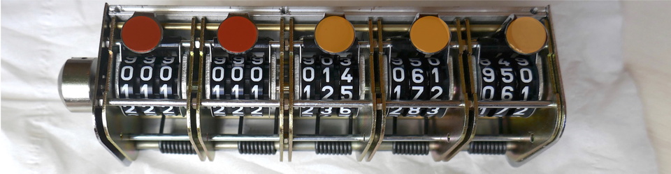
Basically the ‘4060 oscillates with a period of 0.85 seconds. This is Q0 or Φ0. Then Q1 is double by a factor of 2*1 (it divides by two, binary divider), then Q2 by a factor of 2*2 (next binary divider) and Q4 (which is the first available pin) is 0.85s * 2exp4 = 13.6s. Then Q14 is 0.85 * 2exp14 = 0.85 * 16384 ≈ 13926s which is 232 minutes. After half a period initially low then Q14 goes high, which would be after 116 minutes which is about 2 hours.

This scope picture shows Q0 (yellow), Q4 (violet), Q5 (blue) and Q14 (green). I didn’t wait two hours, so Q14 is always low on the picture.
At power-up Q14 needs not even to have a tiny glitch pulse, so I use the ‘4060 reset input MR to handle this. There is a race with the S and the R inputs of the SR NAND latch there, but I have solved it with a longer time constant and then using the same signal to reset ‘4060 and the SR latch. Observe that S (set) and R (reset) inputs need to stay high, then get switch state with low pulses. Therefore notSET and notRESET in the diagram.
After about two hours the SR latch is switched off with the edge of Q14. The RC after D1.3 will do this. With such small capacitors I haven’t used series resistors or diodes to protect the CMOS input, since they do have some protection on chip.
Observe that I have not wired the USB signal cables through the unit. A power bank and a unit being charged could easily decide on a higher voltage than 5V (even if I doubt that a tiny hearing aid charger should want such demanding treatment), which my load resistor isn’t designed for. The ICs are old style CMOS, and they should endure at least 12V. Read about USB and other voltages and power ranges at Stack Exchange here.
I have three modes of the 125 mA dummy load. Mode 1: With the shorting jumper in the upper position, the dummy load will stay while the real load is powered, for about two hours. This draws the most extra capacity from the power battery bank supply. Mode 2 (default): With the jumper in the lower position there would be a duty cycle of 25% or 1/4. I do this with a logical AND of Q4 and Q5 which yields 6.8s on, 20.5s off with a period of 27.3s. This seems to trick most power banks I have tested to let their outputs stay on. And it saves 3/4 energy from mode 1. Mode 3: is when jumper is not mounted. No dummy load, the unit will switch off power to the hearing aid’s charger after about two hours. I have tested two such, one draws 0.5 mA and the other 5 mA at idle – an my unit draws about 0.5 mA. So for the latter charger my unit would be of some help.

Fig.4 – The soldered board
I am still into using soldering boards, instead of shipping a KiCad layout off and get a holed board back. The TR1 and TR2 MOSFET transistors are at the lower left and lower right, standing. The large green part is the CX capacitor of 1uF, a chunky one I found on my old goodies box. It’s a plastic film capacitor of quite high voltage. A assume a ceramic or tantalum would also do.

Fig.7 – Yellow LED power in, red LED dummy load on (1/4 of the time). Enough for max. 30 chargings
OBSERVE
Observe that IATA (International Air Transport Association) requirements is that you must carry a lithium power bank in your hand baggage and its maximum value is 100 Wh or 27000 mAh (see here, here or here). And you can bring max two such units. (Disclaimer: check the sources yourself).
- The two power banks shown in the fig.6 and fig.7 here are a large 20000 mAh (20A h * 3.7 V =74 Wh) and a smaller 3350 mAh (3.35 Ah * 3.6 V = 12.06 Wh). Read about the internal battery elements’ «about 3.7V» and Watt-hour here. Since my box in the 1/4 duty cycle mode would draw 160 mW for two hours (below), plus of course the small power needed by the hearing aid charger (I measured max 7 mA on one) – this adds op to 160 mW + (5 V * 7 mA) ≈ 200 mW for two hours. This is 0.4 Wh. The smaller bank would then be able to deliver max. 12 Wh / 0.4 Wh = 30 chargings, and the larger 74 Wh / 0.4 Wh = 175 chargings. I have not tested this; they are pure desktop calculations
- Also observe that the larger bank in the photo will have its charging level LEDs always on, where on the smaller power bank the LEDs are fast switched off. So banks behave differently!
- Pressing the button on the power bank will indeed lit these LEDs. But this will not necessarily turn the power output on. To restart the power bank to output power again, the USB connector must be unplugged and then plugged in again
- The final unit with the tin box weights 95 grams. It produces little heat. As seen from below 5V * 125 mA = 625 mW (milliwatt) when mode always on during the two hours. If standard duty cycle of 1/4 we’d have 625 mW / 4 ≈ 160 mW. Even the internal temperature raise of the first case is little. Still it should not be kept under the pillow!
- The CAPSTAN tobacco box here is very well suited for the Adafruit #503 size 81 x 51 mm Perma-Proto Half-sized Breadboard PCB soldering board. I love this board, with its thru-plated holes
- I did add a text label on the outside bottom and the inside of the top, for information to the user and any airport screening baggage checker. I haven’t published it here since it’s not tested in real life yet
Future version?
I would perhaps add another ‘4060 oscillator binary counter, so that one of them could control the two hours timing and the other the dummy load. This would give more flexibility, and the dummy load oscillator could run faster. There could be a pot-meter for the frequency and a switch for the duty cycle. This might hit more power banks so that they keep their outputs on for the (two) hours. With two ‘4060, even the 2h timer could have a switch to select between, like 1h, 2h or 3h. Plus of course, a switch to select the dummy load. If all these power banks use the same IC then this could be standardised I guess. But I don’t know which ICs they use. A final point could be to present the dummy load immediately instead of starting with a pause. See «class 3» of the Disclaimer chapter.
Passive original version that you’d have to manually disconnect
Observe that in the Disclaimer chapter you have to be in «class 4». Since I made this unit I made the Updated version times out and draws current intermittently. This does not necessarily make the resistor-only solution below outdated. If you as a start don’t solder the resistors permanently, but make it possible for you to pulse the load by hand, this may help you figure out whether it’s meaningful to make a timed version. In that case it’s worth finding out whether pulsing with about 7 seconds load and 20 seconds no load will make the power bank stay tuned. If so, you are in «class 4».
So: unplug the cable when it’s not needed, and never use it while you sleep! (But if you have a 20 000 mAh power bank, it will survive for 20000 mAh / 125 mA = 160 hours – or let us say 100 hours – so you shouldn’t need to watch over and unplug it the first second after your hearing aid signals that it’s fully charged.)

Fig.1 – Power bank and charger and meter
Here’s what I did. I opened the charging cable, which was an USB-A to USB micro-B cable. (In the future it might be USB-C in the one end. I assume that micro-B will stay with us for a long time). I introduced two resistors in series as 18 Ω + 22 Ω = 40 Ω (Ohm). I call this for a resistor in singular after this. This is often written as 18 + 22 = 40, to differentiate from kOhm etc., which would be 18k+22k=40k. The reason I used two is to avoid them becoming too hot. As you can see from the Ohm’s law calculations:
I=V/R   : 5 V / 40 Ohm   = 0.125 A     = 125 mA
W=V*I   : 5 V * 0.125 A  = 0.625 Watt  = 625 mW
W=R*I*I : 18 Ohm * 0.125 mA * 0.125 mA = 281 mW
W=R*I*I : 22 Ohm * 0.125 mA * 0.125 mA = 343 mW
..is that the 22 Ohm needs to dissipate 343 milliwatt. (Voltage is in Volt, current in Ampere and resistance in Ω or Ohm). So I used resistors that could withstand this (like 400 mW or 500 mW). I soldered on a little board and used heat-shrink tubing around the resistors to avoid any internal short circuits, and also around the whole piece for protection. I can feel it gets a little warmer than my fingers, but that’s all. It is however still definitively not a good idea to keep it under you pillow – give it proper air cooling!
Fig.1 does not show the hearing aid charger. But it does show my new USB meter which tells that the cable itself now draws 0.10A. At 5.09 V it should have shown 5.09 V / 0.040 kΩ = 127.25 mA or 0.13 A, but fair enough. My 40 Ω was pretty accurate. (UNI-T USB Tester, UT658DUAL. Disclaimer)
Why does it work? The hearing aid charger gets its needed constant 5V from the power bank at all times, even when the charger’s own power consumption goes to almost zero (*). The power bank continues to feed 5V into the cable’s internal resistor, which draws 125 mA. This is so much that the power bank won’t ever give up on it. Even if the hearing aid charger might draw only 5 mA, the sum of 125 + 5 mA will of course be above the power bank’s cut-off limit, since 125 mA is so.
(*) Say proportional to milliamps consumption, since power here is milliamps times the constant 5V.
A better idea would have been to produce a cable for this, one that contained some electronics that cut off the resistor when the user pressed a button, and then remembered the current drawn by the other consumer, and used it the next time it was powered.
Norwegian: hvordan få en lader til høreapparater til å kunne blie ladet fra en powerbank som slutter å levere strøm når nivået går under en viss terskel.
 Aside: This figure shows the parallel resistor RL. – which is what we would call our resistor as well. I actually drew this picture for Wikipedia. I drew it two times, after I first had photographed an old analogue milliamp-meter’s face and used that photo in the figure. I wasn’t allowed to use it, because I could not find the proper owner of that face. Fair enough. So I made thsi second drawing instead, from scratch. I am Aclassifier a Wikipedia Commons (here).