
Contents
This note is in group E-FUN and MINIATURES. I wanted my nice little lighthouse to flash all year round, so I needed to replace the button battery with an AC adapter of some sort. Please see Standard disclaimer.
Simple a 6V to 3V adapter

Fig.1 – Still from movie, to freeze a flash
This beautiful flashing lighthouse (45 * 44 * 50 mm) moulded into a polished acrylic block by Wintrebert in France has not flashed much. I have wanted to save the battery. I would observe the flashes only some seconds each day anyway, why burn a nice lithium battery for that? We bought it in 2017 in the TRANSPARENCE shop in Nice. I have more of the sort, but they don’t have any embedded electronics. Since then I have only needed to replace the 3V CR2032 lithium cell once, after a week or two. But a lighthouse that isn’t flashing all the time, what kind of a lighthouse is that? Aside: 24/7 – provided it’s dark?
Observe, there is only one lighthouse in the block, let not the pictures fool you.
My purpose with this note is not to emphasise on the model per se, but the replacement of the button battery. Generally speaking, I hope the note might be of help for any such gadget that you feel would need to be on no less than dark hours 24/7.
That being said, here’s about the production process. It is truly amazing that these pieces are so elegant:
«All Wintrebert’s inclusions are made of a resin called Methyl Methacrylate or Plexiglass, Altuglass, Perspex, Lucite. The resin is catalysed, then heated to harden and support the weight of the chosen item to include – music instruments, exploded watches, divers, sailing models, fishes, etc. A second acrylic resin is melted in the cast which is then put in an oven at 120°C for eight hours. The heat welds successive layers together to hold it all in place. It shrinks by 10% when it cools down, which means Wintrebert must sand and polish each side by hand to give it a neat finish. Plexiglas being solvent, many objects would melt in this process, so Wintrebert casts each of them in bronze or brass first in his foundry nearby.»
From https://www.wintrebert.com/atelier-gb.html (21Apr2020)

Fig.2 – Lighthouse, battery adapter, circuit board and box
I solved this in an embarrassingly crude and simple way. If you want something advanced, there are DC/DC converters, like the AP7332 or MIC5213 linear regulators. Here I use no active regulator, just a series resistor since the power consumption is so low. Then a capacitor to make it survive one flash without input voltage. This will also ensure that it has stiff enough power for the short flash every four seconds. Then, four old signal diodes 1S920 which I found in a box. Together they make up for a zener diode that would limit the voltage to about 3V.
Actually, the series resistor and the «zener» would constitute a simple passive regulator. It’s called a shunt regulator, used for very simple low-power applications. Aside: the shunt term originates because the parallel shunt diodes D1-D4 are diverting current away from the load (Wikipedia). Although my solution uses the real diodes in the other direction than the zener diode shown there. Stay tuned.
At first I had to make some replacement for the CR2032 battery. I had some plain glass fibre PCB board material with no copper and no through-holes, making it impossible to short the «poles». Then it was easy to fasten two wires across, one on each side, and pick them up with two cables. I had to insert some kind of a slider at the bottom side. I fastened it with some dental floss through two holes as well. It works ok, but it’s not quite ready for production, to say it mildly. You would have to find a solution for your battery holder anyhow, so I am not showing the detail here.
The first thing I did was to «tune» the 1S920 silicon diodes with the diode measuring on my multimeter. I found four that were as close to each other as possible. This measures forward-bias, meaning that the current flows in the normal direction. Some measured 0.5xV and some 0.6xV, so I selected those that were about 0.63V – 0.66V, for somewhat even distribution. I assume that the meter uses about 1 mA during this measurement. (Update: I measured it with another meter, it was 0.92 mA with the diode in the circuit, 1.29 mA when shorted and beeping.) I would like to have about 0.75V over each, so I increased the current by lowering R1 (below). Aside: germanium or Schottky diodes would have had smaller forward voltage, so they would not here have been as useful as these silicon diodes. One can do this to some extent with a diode (Wikipedia). A kind of variable voltage reference by tuning the current. I ended up with 330 Ohm. The current would then be (6V – 3V = 3 V) / 0.33 mA ≈ 9 mA. This is no problem for 1S920 (data sheet). I remember this diode from the eighties, we used it a lot. I seem to have loads of these relics.
Follow the same procedure if you go from 5V or other input.
I now have a voltage reference with a quite high temperature coefficient, kind of a small thermometer. The four forward biased diodes in series would see about 4 * (−2 mV/˚C) = −8 mV/˚C (Wikipedia). I think the electronics inside the lighthouse should endure, probably some 2V to max 4V. I did not want to end up with a dark lighthouse, though.
Aside: A zener diode of 3.0V could have been used, and it would have been a better regulator since it has a sharper knee in its reverse voltage vs. current curve than a diode would have for its similar forward voltage vs. current. But I could not find any 3V zener in my old box. I had several BZY88 in ranges 2.7V to 8.2 V, but no 3.0V. I would have needed only one zener, and it would, as already mentioned, have been reverse-biased, with the flat, bent cathode on the top on the diagram (Wikipedia). I have thrown a loose zener into the diagram (below). In the early days, when I needed a reference I tried to use 4.7 V, because that’s where the temperature coefficient is closest to zero. Inspecting ancient BZY88 data sheet (here) there is none at zero, but the temperature coefficient crosses the zero line between 4.3 and 4.7V. However, my diodes should be ok for this design.
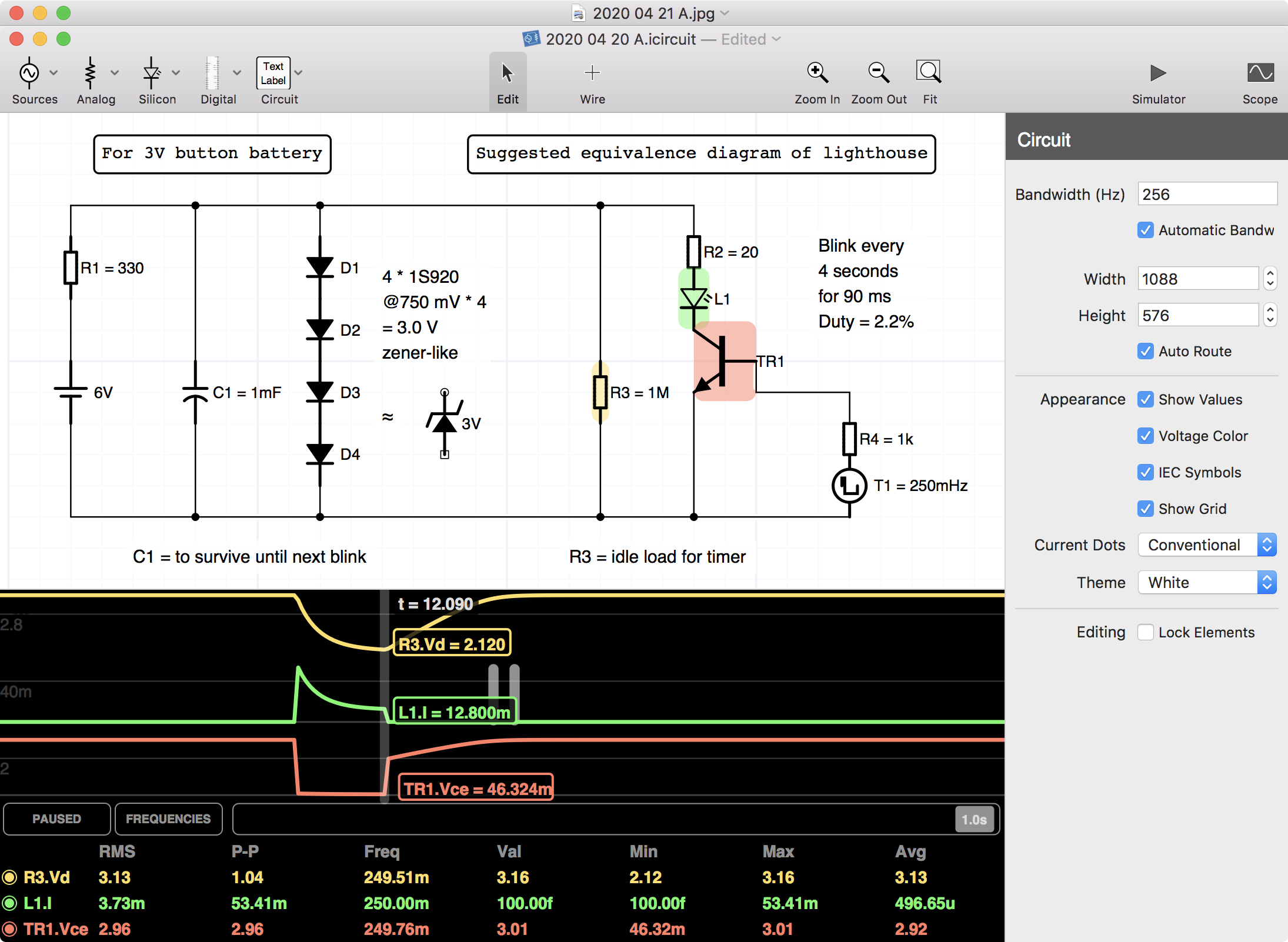
Fig.3 – From the iCircuit app
Above I have drawn the left part, which is 6V to 3V electronics together with the right part, which is supposed to be a suggested equivalence diagram of what’s inside the lighthouse. I tuned R2 all the way down to 20 Ohm to get a voltage curve that looked like the measured (below). The max current the LED L1 is 53.4 1mA, but the RMS value (Wikipedia) is only 3.73 mA. So the LED won’t burn. But I think it’s a lot for the maximum. But the flash is quite distinct. The button battery CR2032 data sheet (here) says its capacity is 240 mAh to 2.0V. Assuming the timer draws nothing compared, the battery would last 240 mAh / (53 mA * 2.2%) = 240 mAh / 1.16 mA = 206 hours = 8.6 days. My back-of-the-envelope calculation (Wikipedia) tells me a week is too short. But then, not missed by a factor of 10. So for the first iteration it’s ok. I haven’t measured the real current pulse.
A complicating factor is the internal resistance of the CR2032. According to the data sheet it is around 10 Ohm. If I set up an iCircuit simulation with stiff 3V instead of the 6V converter and take R2 from 20 Ohm to 20 + 10 = 30 Ohm then the max current decreases from 54 mA to 37 mA. The duration of the battery would in that case be 240 / (37 * 0.022) = 299 hours = 12 days.
Update: I did measure the real current, see Postscript. But read on first:

Fig.4 – The pulse across C1 as seen on a (Siglent SDX 1204X-E oscilloscope)
But here is the measurement of the voltage across C1. The voltage drop is -0.98 V, and it flattens out at absolute 2.19V. The reason is the LED, which has a saturation voltage of around 2.2V. In the iCircuit model above I have set the LED voltage at 2.1V. The flashing pulse is 87ms long and it repeats every four seconds. Duty cycle = 4000/87 ≈ 46 and 100/46 ≈ 2.2 %. When the pulse has finished then C1 is charged through R1. Here is a formula to calculate things over, for some kind of check:
Q (charge) = C (Farad) * U (Volt) = I (Ampere) * t (seconds)
t = (C * U) / I
t = (1000 uF * 0.7 V) / (3.5V / 330 Ohm) = 0.07 s = 70 ms
This is up to about 70% filing. This is ok. The landscape and the map fit fairly well.

Fig.6 – Still from movie
I soldered R1, C1 and D1-D4 plus a connector on a small circuit board. And put it in a plastic box.
Live
Almost like sitting in a small boat!
Prolog

Fig.6 – A plasma lamp use to use the 6V
Now, why in the world did I have a 6V available? Because, as a prolog to this..
..I had added a permanent 6V input to a plasma lamp. I had made a nice acrylic shelf for it, above my iMac.
The problem is that it is a rather powerful radio transmitter, sending at who knows which frequencies.
It caused the quite new Apple A1657 Magic Mouse 2 Bluetooth mouse to (some times) cause my cursor to flutter around on my screen. Not nice at all I. No, there was no error message.
It also caused the closest smoke detector of the Autronica BS-50 wired fire detection system (a prototype from my desk from 1992, flawlessly working in this house since then (I have replaced some dusty detectors and some lead-acid backup batteries)) to lose contact with the detector. Not nice at all II. Yes, there was an error message.
Now I know why they did not supply the plasma lamp with that permanent 6V! I am afraid that I again may have outsmarted myself so much that I now have reverted to the internal four AA batteries and the switch! I may just about allow myself and grandchildren some moments of wonder of that plasma wonder. Did you know, there’s probably more plasma out there than anything else? (Wikipedia). Even more, it’s now not on the high shelf anymore. But the lighthouse is.
Postscript
Measuring the current
I could’t be true to myself as an engineer without actually measuring the current. So I added a 1 Ohm resistor in the plus wire (for 1A / 1V = 1 mA per 1 mV) and made two measurements. (Aside I did this by soldering three 3 Ohm resistors in parallel (Wikipedia). The multimeter showed 1.3 to 1.1 Ohm depending on how hard I pressed. Then, I tested what it said for shorted probes. 0.3 to 0.1 Ohm depending on how much I pressed! So, the probes are about 0.3 to 0.1 Ohm).
The first measurement is one with an ideal 3V power (I have a Rapid PS 1525S that I love for everything except for the noisy fan). I then placed scope ground on a common plus and had the voltage seen «down» from it. The voltage is yellow and the current is violet:

Fig.8 – Stiff 3V voltage and current of pulse over 1 Ohm (54.8 mV = 54.8 mA) (Siglent scope)
I was surprised to see that the model and the real came out about the same! Model was 53.41 mA (above) and measurement is 54.8 mA (here). I’d say they are equal!
However, when I replaced the stiff 3V power with my circuitry it was not as nice:

Fig.7 – Weak «my circuit» power showing voltage and current of pulse over 1 Ohm (Siglent scope)
The electronics tries to grab about 55 mA but flattens out to 13 mA. However, I would not be able to tell whether the flash itself looks any different. There may be a capacitor inside the lighthouse that in case might be meant to keep the timer alive over a weak battery. I am not certain how the inner resistance of a lithium cell goes as is looses charge.
A warning: puff and over!
I mailed with the TRANSPARENCE shop and the lady told that a customer once had modified the lighthouse to such an extent that the light was shining continuously. This customer must have picked out the electronics, which I never even thought of. It had caused the plexiglas to break! (This sound strange to me as even that would only cause 55 mA * 2.1V = 116 mW. But perhaps, the LED may break because it’s not cooled properly, and then perhaps the plexiglas broke first? Also, the customer may have powered the LED from the battery without any series resistor, causing a max current only limited by the internal resistance of 10 Ohm of the battery).
Conclusion and further work

Fig.9 – Still from movie, to freeze a flash. Box is gone, shelf and screen are new
The lighthouse became so nice that I had to make a new acrylic shelf, without the holes for the plasma lamp that the other had. I also added a shielding wall, made from a 9 mm fire EXIT sign, with the EXIT foil removed. It’s supposed to get light from the top and disperse it beside the text. There are two screws in the shield with the heads cut off, going into two holes in the shelf – so it’s easy to just lift the shield up.
What about making it flash 24/7 – but only when it’s dark? Perhaps my next E-FUN project?
And my coarse and simple little 3V button cell adapter is as bad or as good as it is. But it works!
▢